Installation and setup, cont’d – Extron Electronics MLA-VC10 User Manual
Page 16
MLA-VC10 • Installation and Setup
Installation and Setup, cont’d
2-4
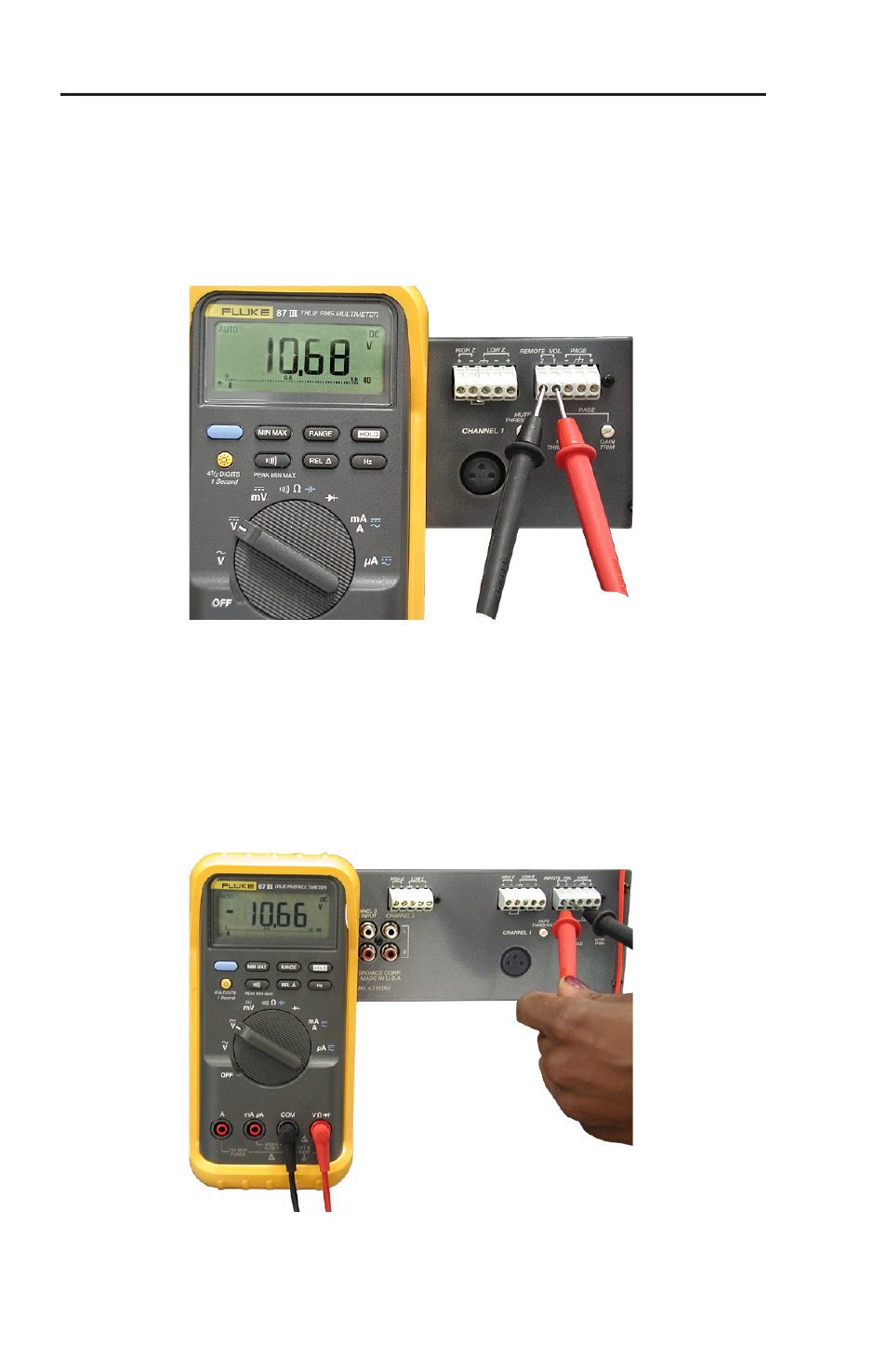
Measuring voltage for a Peavey UMA 35T II
amplifier
Control Terminals for Peavey amplifiers usually consist of two
screw terminals. In the example shown below, they are labeled
"Remote Vol". Use a voltmeter, set to VDC, to measure the
voltage.
Figure 2-3 — Measuring control voltage for a Peavey
UMA 35T II: Meter probes are oriented correctly.
In figure 2-3, the measured voltage is positive, so the right
terminal is the signal connection and the left terminal is ground
connection. Write down the measured voltage and which
terminal is ground as this will be important when you set the
DIP switches. If the voltage is negative (see figure 2-4), the
meter's probes are touching the wrong terminals.
Figure 2-4 — Measuring control voltage for a Peavey
UMA 35T II: Meter probes are oriented incorrectly.
Meter probes
correctly oriented
Meter probes
incorrectly oriented
- AVTrac Corner Cut Solution (2 pages)
- AVTrac Demonstration Kit (2 pages)
- AVTRac End Ramp and Cable Pass-Through Kits (1 page)
- AVTrac Extension Kit (15 pages)
- 1U and 2U Rack Plate (1 page)
- Under-Desk Mounting Bracket (1 page)
- AAP Wiring Guide 68-1054-01 (1 page)
- AAP Wiring Guide 68-1052-01 (1 page)
- AAP Wiring Guide (XLR connectors) (1 page)
- AAP 314 (1 page)
- AAP 301 (1 page)
- AAP Wiring Guide 68-1055-01 (1 page)
- AAP Wiring Guide 68-1058-01 (1 page)
- AAP Wiring Guide 68-1059-01 (1 page)
- AAP-MAAP Rev. A (1 page)
- AAP-MAAP Rev. D (1 page)
- MD Floor Box AAP Bracket Kit AAP 100 MD (1 page)
- AC 100 Power Module Series (1 page)
- AAP 103 Extron Ackerman AKM UK Faceplate Kit (1 page)
- ACMP 100 (2 pages)
- Active Audio AAP (1 page)
- AKM UK Series (4 pages)
- Audio AAP Wiring Guide (1 page)
- Audio Connector Rev. A (2 pages)
- Audio Connector Rev. G (1 page)
- AVTrac Extra Channel Kit (2 pages)
- AVTrac Raceway Transition (2 pages)
- AVTrac Retrofit Transition Adapter (2 pages)
- AVTrac Trim Ring-Rough-in Adapter (2 pages)
- AVTrac Above Floor (1 page)
- BB 1 (2 pages)
- BB 1000M (2 pages)
- BB 700M (2 pages)
- BB 710M (2 pages)
- Blank Rack Panel (1 page)
- BNC to 15-Pin HD (1 page)
- BNC-5 RC Termination (1 page)
- Cable Cubby 1200 (6 pages)
- Cable Cubby 200 (18 pages)
- Cable Cubby 300C (27 pages)
- Cable Cubby 500 (6 pages)
- Flexible Conduit Kit (2 pages)
- Cable Cubby Lid and Trim Ring Replacement Kit (for 300C, 300S, 600, 800) (1 page)
- Cable Cubby Setup Guide (4 pages)
- Cable Cubby Single Space AAP Bracket Kit (1 page)