Wiring, Wiring the mlc/power connector, Wiring the mlc/power connector -8 – Extron Electronics MLA-VC10 User Manual
Page 20: Installation and setup, cont’d
MLA-VC10 • Installation and Setup
Installation and Setup, cont’d
2-8
Wiring
Wiring the MLC/Power connector
N
Power and communications cables should be at least
18 AWG.
N
If the cable has a drain wire, it should be ground at
both ends. To avoid introducing noise and static into
audio channels, the chassis of the MediaLink controller
(if used), the power supply, the MLA-VC10, and the
amplifier or mixer should all share a common ground.
N
The 12 VDC, 1 amp power supply kit (PN 70-055-01)
provides power for both the MLA-VC10 and the MLC.
It is not included with the MLA-VC10.
To connect the MLA-VC10 to the power supply and an Extron
MLC device or a third party control device follow these
instructions and figures 2-8 to 2-11.
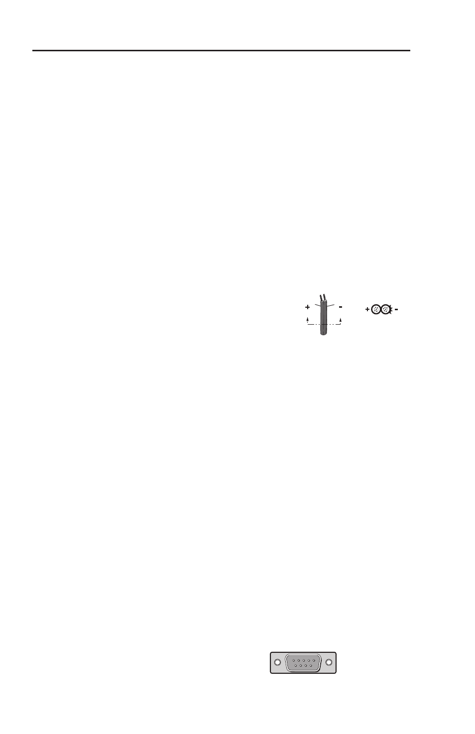
Check the polarity of the wires from
the power supply and connect them to
the captive screw power input on the
MLA-VC10 front panel. If the power
supply is also providing power for an MLC device, connect the
same captive screw sockets to the power input on the MLC.
Connect the Transmit (Tx) socket (labeled "A") on the front panel
of the MLA-VC10 to the Receive (Rx) socket (also labeled "A")
on the MLC device. Connect the Receive socket (labeled "B") on
the front panel of the MLA-VC10 to the Transmit socket (also
labeled "B") on the MLC device.
If the MLA-VC10 is to be connected to a third-party control
device:
connect the Transmit socket on the front panel of the MLA-
VC10 to the Receive socket of the control device
connect the Receive socket of the MLA-VC10 to the Transmit
socket of the control device
connect the ground socket of the MLA-VC10 to the ground
socket on the control device
The MLA-VC10 can be connected to a computer serial port
using a DB-9 connector that is wired as shown in the figure
below.
•
•
•
Male
9 Pin D Connector
Pin Configuration
Male
RS-232
Pin
Function
2
Transmit (Tx)
3
Receive (Rx)
5
Ground (Gnd)
1 5
6 9
Power Supply
Output Cord
SECTION A–A
Ridges
Smooth
A
A