Preliminar y, Installation, cont’d, Dvcm 50 • installation 2-6 – Extron Electronics DVCM 50 User’s Manual User Manual
Page 14
Installation, cont’d
DVCM 50 • Installation
2-6
PRELIMINAR
Y
3
.
Attach a 3.5 mm, 5-pole captive screw connector to each end of the cable.
Only three wires are required:
•
A (DVCM) to A (IR Link)
•
B (DVCM) to B (IR Link)
•
C (DVCM) to D (IR Link)
4
.
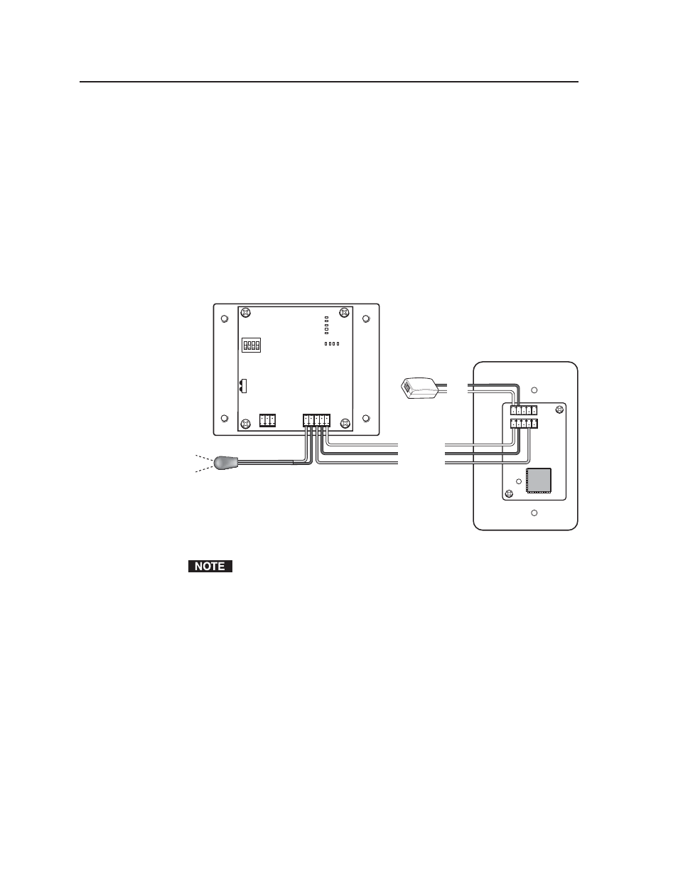
Connect the wires as shown in the illustration below. Connectors are included
with the IR Link, but the cable must be purchased separately.
5
.
Plug one 5-pole connector into one of the IR Link’s communications
connectors.
6
.
Plug the other 5-pole connector into the rear panel control port of the
DVCM 50.
IR Link (Rear Panel)
DVCM 50 (Rear Panel)
1
1
2
3
8
4
2
1
E
4
ON
2 3 4
IR OUT
GND
IR IN
GND
+ 12V
GND
Rx
Tx
GND
+12V
A
B
D
GND
+12 V
A
B
C
IR IN
Wiring the IR Link for IR 452 remote control
Connect a maximum of one IR Link or IRL 20 to the DVCM 50.
- AVTrac Corner Cut Solution (2 pages)
- AVTrac Demonstration Kit (2 pages)
- AVTRac End Ramp and Cable Pass-Through Kits (1 page)
- AVTrac Extension Kit (15 pages)
- 1U and 2U Rack Plate (1 page)
- Under-Desk Mounting Bracket (1 page)
- AAP Wiring Guide 68-1054-01 (1 page)
- AAP Wiring Guide 68-1052-01 (1 page)
- AAP Wiring Guide (XLR connectors) (1 page)
- AAP 314 (1 page)
- AAP 301 (1 page)
- AAP Wiring Guide 68-1055-01 (1 page)
- AAP Wiring Guide 68-1058-01 (1 page)
- AAP Wiring Guide 68-1059-01 (1 page)
- AAP-MAAP Rev. A (1 page)
- AAP-MAAP Rev. D (1 page)
- MD Floor Box AAP Bracket Kit AAP 100 MD (1 page)
- AC 100 Power Module Series (1 page)
- AAP 103 Extron Ackerman AKM UK Faceplate Kit (1 page)
- ACMP 100 (2 pages)
- Active Audio AAP (1 page)
- AKM UK Series (4 pages)
- Audio AAP Wiring Guide (1 page)
- Audio Connector Rev. A (2 pages)
- Audio Connector Rev. G (1 page)
- AVTrac Extra Channel Kit (2 pages)
- AVTrac Raceway Transition (2 pages)
- AVTrac Retrofit Transition Adapter (2 pages)
- AVTrac Trim Ring-Rough-in Adapter (2 pages)
- AVTrac Above Floor (1 page)
- BB 1 (2 pages)
- BB 1000M (2 pages)
- BB 700M (2 pages)
- BB 710M (2 pages)
- Blank Rack Panel (1 page)
- BNC to 15-Pin HD (1 page)
- BNC-5 RC Termination (1 page)
- Cable Cubby 1200 (6 pages)
- Cable Cubby 200 (18 pages)
- Cable Cubby 300C (27 pages)
- Cable Cubby 500 (6 pages)
- Flexible Conduit Kit (2 pages)
- Cable Cubby Lid and Trim Ring Replacement Kit (for 300C, 300S, 600, 800) (1 page)
- Cable Cubby Setup Guide (4 pages)
- Cable Cubby Single Space AAP Bracket Kit (1 page)