Dsp processing and signal flow, Line input signal chain, Dsp processing/signal flow – Extron Electronics DMP 44 LC User Guide User Manual
Page 20
DSP Processing and Signal Flow
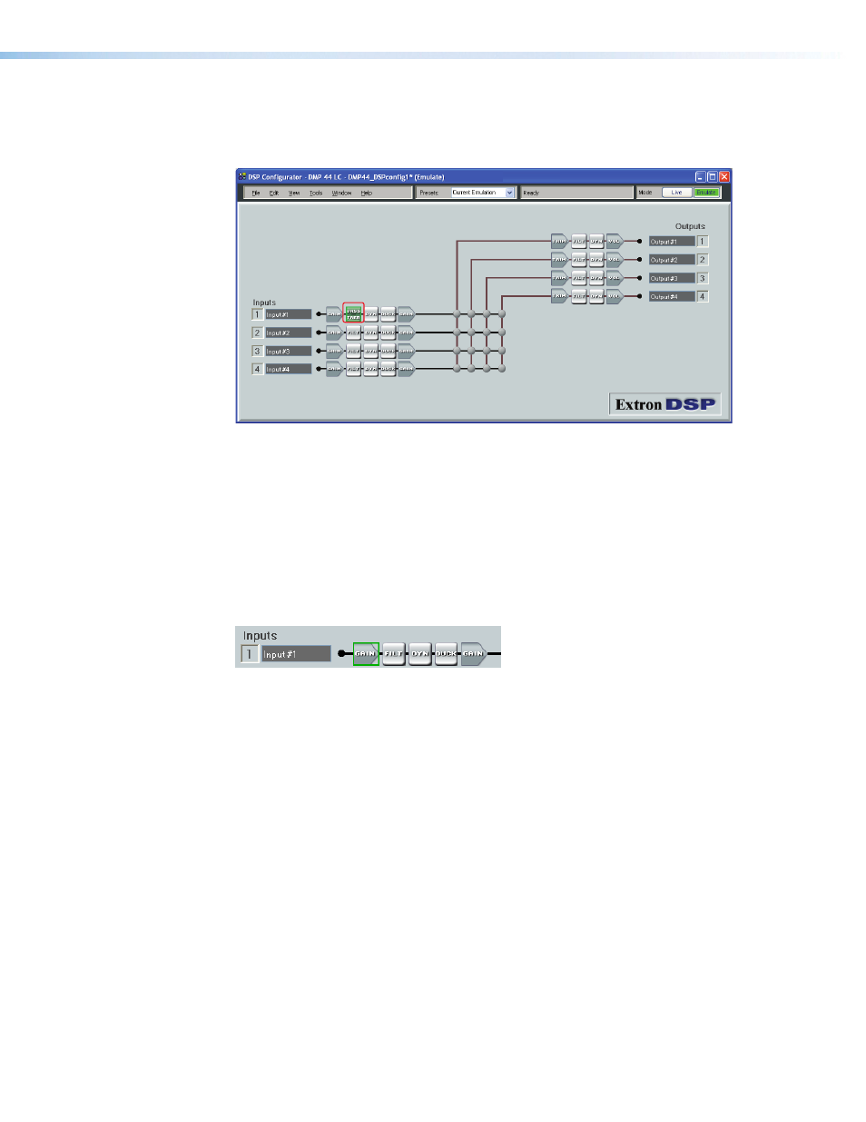
The diagram below shows the signal flow and DSP processing per signal chain. Signal
chains and the matrix are described in the following sections.
All signal routing, processing, and level control (gain/trim/volume), are accomplished using
software control from a PC connected to the DMP 44 LC via the USB configuration port
or the RS-232 port. The DSP Configurator program provides complete control while SIS
commands provide more limited control.
This section describes the signal processing including parameter ranges, and how to
mix inputs and outputs using the DSP Configurator control program. To install the DSP
Configurator program (see the “
Line Input Signal Chain
Input signal chain GUI elements from left to right are as follows:
•
Gain (GAIN) — Mono gain control with a range from -18 to +24 dB includes a mute
button. Step resolution is 0.1 dB. A polarity switch (+ or -) is provided. Gain control is
provided pre-meter and mute control is provided pre-meter.
•
Filter (FILT) — Up to three filters can be inserted in any combination of High Pass,
Low Pass, Bass & Treble shelving (tone), or Parametric Equalizer.
•
Dynamics (DYN) — One compressor per block per channel. Dynamics processors vary
the dynamic level (the range of loudest to softest signals).
•
Ducking (DUCK) — One ducker per block, per channel. Each ducker can function as
either a source or a target. Three levels of priority are available, where a ducker can
function as both a source and a target (as an example, one source may be ducked by
another source, and also trigger ducking on program channels).
•
Gain (GAIN) — One pre-mixer gain control per channel with a range of -100 dB to
+6 dB. The step resolution is 0.1 dB.
DMP 44 LC • Operation
14