Extron Electronics DMP 44 LC User Guide User Manual
Page 12
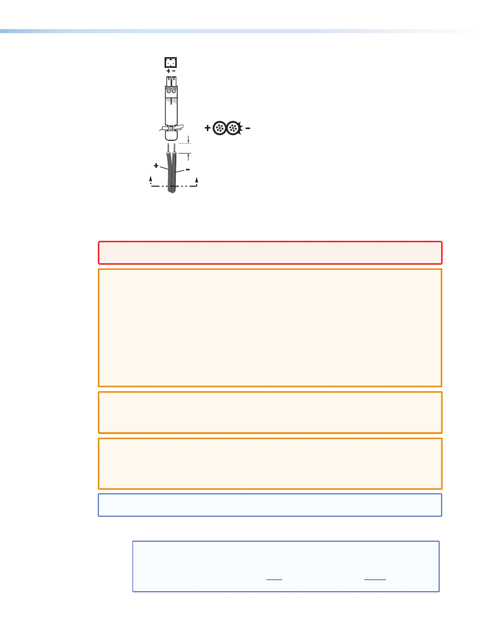
SECTION A–A
A
A
Power Supply
Output
Cord
2-Pole Captive Screw
Connector
Ridges
Smooth
Tie Wrap
3/16”
(5 mm) Max.
Figure 2.
Power Supply Wiring
WARNING: The two power cord wires must be kept separate while the power supply is plugged
in. Remove power before wiring.
CAUTIONS: • Always use a power supply supplied by or specified by Extron. Use of an
unauthorized power supply voids all regulatory compliance certification and may
cause damage to the supply and the end product.
• Unless otherwise stated, the AC/DC adapters are not suitable for use in air
handling spaces or in wall cavities. The power supply is to be located within the
same vicinity as the Extron AV processing equipment in an ordinary location,
Pollution Degree 2, secured to the equipment rack within the dedicated closet,
podium or desk.
• The installation must always be in accordance with the applicable provisions of
National Electrical Code ANSI/NFPA 70, article 75 and the Canadian Electrical
Code part 1, section 16. The power supply shall not be permanently fixed to
building structure or similar structure.
CAUTION:
When connecting the power supply, voltage polarity is extremely important.
Applying power with incorrect voltage polarity could damage the power supply and
the DMP 44 LC. Identify the power cord negative (ground) lead by the ridges on the
side of the cord or a black heat shrink wrapping around it.
CAUTION:
The length of the exposed (stripped) copper wires is important. The ideal length
is 3/16 in (5 mm). Longer bare wires can short together. Shorter wires are not as
secure in the direct insertion connectors and could be pulled out.
Do not tin the stripped power supply leads. Tinned wires are not as secure in the
captive screw connectors and could be pulled out.
NOTE: To verify the polarity before connection, check the no load power supply output with a
voltmeter.
Use the supplied tie-wrap to strap the power cord to the extended tail of the connector.
NOTE: To avoid losing adjustments when configuring the DMP 44 LC via
SIS commands issue a 2FF or if using the DSP Configurator, select
Tools > Save Changes to Device
to store the latest changes to the
device. Wait several minutes after saving the adjustments before disconnecting
power.
DMP 44 LC • Installation
6