Front panel operation, Rear panel operation, Power cycle – Extron Electronics DMP 44 LC User Guide User Manual
Page 16: Front panel operation rear panel operation
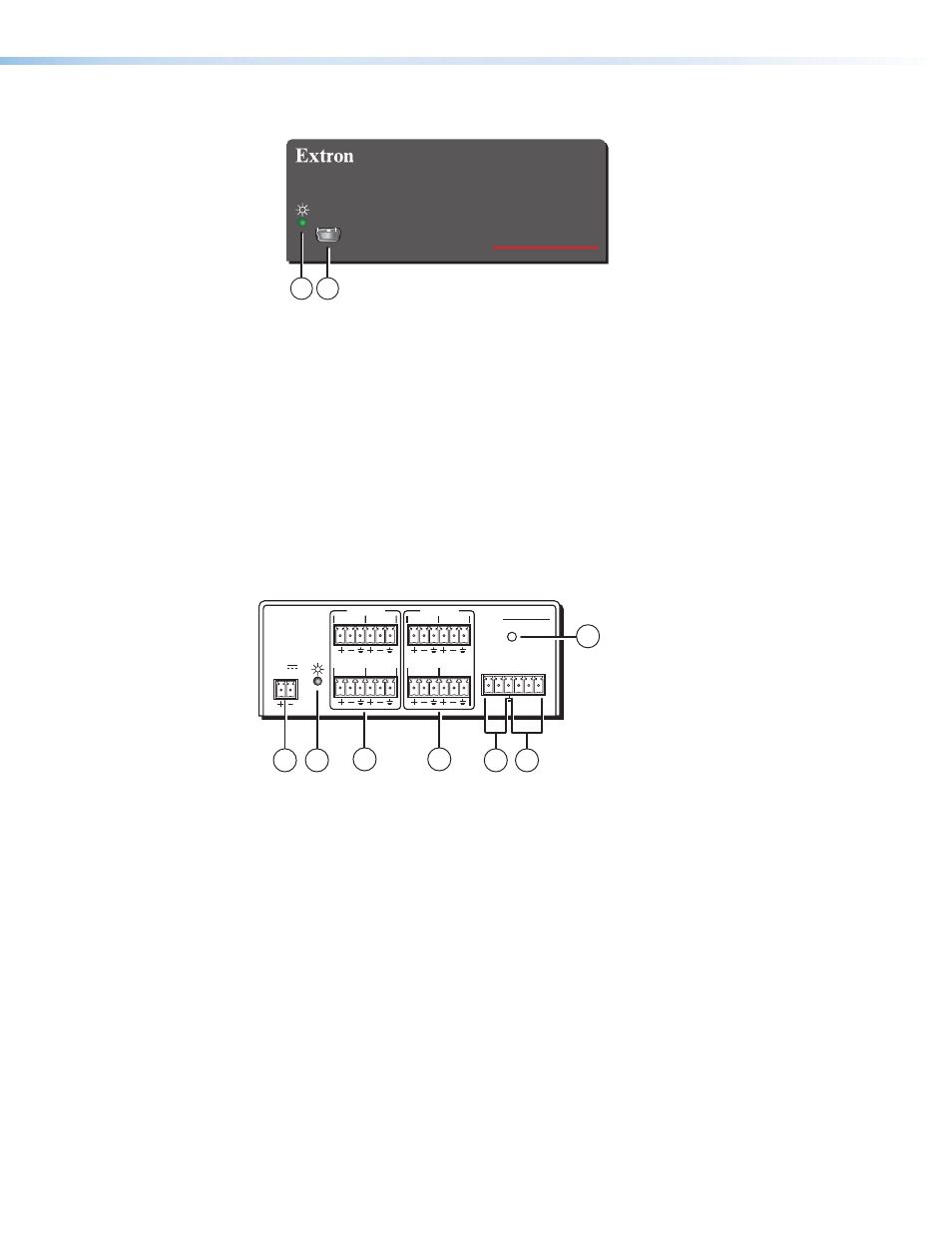
Front Panel Operation
DMP 44 LC
DIGITAL MATRIX PROCESSOR
CONFIG
1
2
Figure 6.
DMP 44 LC Front Panel
a
Power/Reset LED — Green power indicator lights when the DMP 44 LC is
operational.
b
Configuration connector — The USB 2.0 port uses a mini type-B connector to
connect to a host computer for control. The DMP 44 LC USB driver must be installed
prior to using the port (see the “
The DMP 44 LC appears as a USB peripheral with bi-directional communication. The
USB connection can be used for software operation (see “
), and SIS control, (see “
Rear Panel Operation
DMP 44 LC
RESET
Tx Rx 1 2 3
RS-232 DIGI IN
3
4
1
2
3
4
1
INPUTS
2
OUTPUTS
POWER
12V
0.3A MAX
7
1
2
3
4
5
6
Figure 7.
DMP 44 LC Rear Panel
a b c d e f
—
See the “
Rear Panel Features and Cabling
“section for further
details.
g
Reset — The reset actuator initiates system reset (see the “
section for additional information).
Power Cycle
Current mixing and audio processor settings — the current state of the device — are saved
in nonvolatile memory. When the unit is powered off, all settings are retained. When the
unit is powered back on, it recalls settings from the nonvolatile memory. If a configuration
was in process during the power down, these saved mix, audio level, and audio DSP
processor settings become active.
On power up, the power/reset LED (b) lights solid when the unit is available for operation
or configuration.
DMP 44 LC • Operation
10