Xylem IM255 AQUAVAR Intelligent Pump Controller User Manual
Page 93
Option
Function
[169]
Auto mode
[180]
Clock Fault
[181]
Prev. Maintenance
[189]
External Fan Control
[190]
No Flow
[191]
No Water/Loss of Prime
[192]
Under Pressure
[193]
Sleep Mode
[194]
Broken Belt
[195]
Bypass Valve Control
[196]
Fire Mode
[197]
Fire Mode was Act.
[198]
Drive Bypass
[211]
Lead Pump Alternate1
[212]
Fixed Speed Pump 1
[213]
Fixed Speed Pump 2
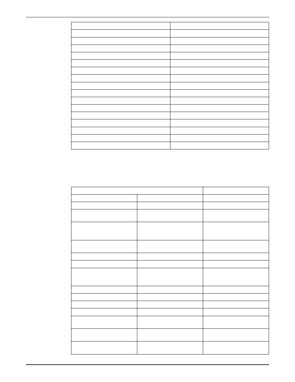
Analog output
The analog output (AO 42, parameter 6–50) can be configured to output various
controller parameters. This output is a current output (0–20mA or 4–20mA). Refer to the
Common Terminal Wiring section in this manual for details on wiring. The list of analog
output configuration options is shown below.
Option
Function
[0]*
No operation
[100]
Output freq. 0–100
0–100 Hz, (0–20 mA)
[101]
Reference Min-Max
Minimum reference — Maximum
Reference, (0–20 mA)
[102]
Feedback +–200%
–200% to +200% of [20–14]
Maximum Reference/Feedb., (0–20
mA)
[104]
Torque 0–Tlim
0–Torque limit ([4–16] Torque Limit
Motor Mode), (0–20 mA)
[105]
Torque 0–Tnom
0–Motor rated torque, (0–20 mA)
[106]
Power 0–Pnom
0–Motor rated power, (0–20 mA)
[107]*
Speed 0–HighLim
0–Speed High Limit ([4–13] Motor
Speed Limit [RPM] and [4–14] Motor
Speed High Limit [Hz]), (0–20 mA)
[113]
Ext. Closed Loop 1
0–100%, (0–20 mA)
[114]
Ext. Closed Loop 2
0–100%, (0–20 mA)
[115]
Ext. Closed Loop 3
0–100%, (0–20 mA)
[130]
Out frq 0–100 4–20mA
0–100 Hz
[131]
Reference 4–20mA
Minimum Reference — Maximum
Reference
[132]
Feedback 4–20mA
–200% to +200% of [20–14]
Maximum Reference/Feedb.
[133]
Motor cur. 4–20 mA
0–Inverter Max. Current ([16–37] Inv.
Max. Current)
Operation
Aquavar
®
Intelligent Pump Controller INSTRUCTION MANUAL
91