Xylem IM255 AQUAVAR Intelligent Pump Controller User Manual
Page 38
A common use of two pressure transducer feedback signals is to take the difference
between the signals to create a differential pressure transducer. To implement a
differential pressure transducer with 2 pressure transducers, set parameter [20-20]
Feedback Function to Difference. The controller will calculate the feedback value as
Feedback 1 Source [20-00] – Feedback 2 Source [20-03]. Be sure to set all unused
feedback sources to No Function (parameters 20-00, 20-03 or 20-06). The parameter
listing that follows shows how to configure the additional transducer.
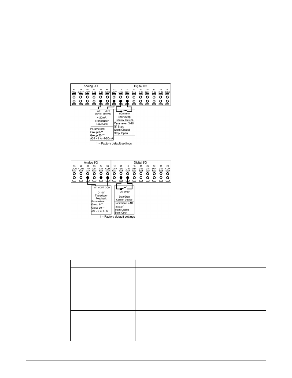
• Analog inputs can be configured using the Start-Up Genie.
• Be sure to properly set the analog input configuration switch prior to using the analog
input. Refer to the Analog input configuration (Switches A53 and A54) for details.
Figure 21: Connections for adding 4–20 mA transducer feedback to AI 54
Figure 22: Connections for adding 0–10 V transducer feedback to AI 54
In order to set up the controller for closed loop control based on the feedback from an
external transducer, set the following parameters:
Table 6: Parameter settings to enable an additional transducer on AI 54
Parameter Number
Parameter Description
Set To
6-24*
Terminal 54 Low Ref./Feedb. Value
Minimum transducer feedback value.
For example, for a 0-300psi
transducer, set to 0.
6-25*
Terminal 54 High Ref./Feedb. Value
Maximum transducer feedback
value. For example, for a 300psi
transducer, set to 300.
6-27*
Terminal 54 Sensor Fault
Enabled
20-03
Feedback 2 Source
Analog Input 54*
20-05
Feedback 2 Source Unit
Units for the second feedback source.
For a differential pressure transducer,
use the same units as found in 20-02,
psi is default
Electrical Installation
36
Aquavar
®
Intelligent Pump Controller INSTRUCTION MANUAL