Control terminal functions, Analog input 53, Jumper terminals 12 and 18 – Xylem IM255 AQUAVAR Intelligent Pump Controller User Manual
Page 33
130BT310.10
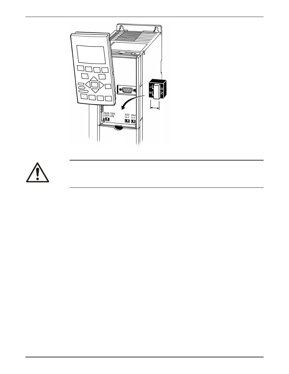
Figure 13: Configuration switch location
WARNING:
Some option cards available for the unit may cover these switches and must be removed
to change switch settings. Always remove power to the unit before removing option
cards.
Control terminal functions
Frequency converter functions are commanded by receiving control input signals.
• Each terminal must be programmed for the function it will be supporting in the
parameters associated with that terminal.
• It is important to confirm that the control terminal is programmed for the correct
function. See the Local control panel section for detail on accessing parameters and
frequency converter section for details on programming.
• The default terminal programming is intended to initiate frequency converter
functioning in a single pump, constant pressure operating more.
Analog input 53
The default operating mode of the frequency converter is Single Pump, constant pressure
mode. In this mode a feedback signal from a transducer, PLC or other device is required
on Analog Input 53 (AI 53). The default settings for AI 53 allow the use of a 300psi,
4-20mA pressure transducer.
When using the supplied pressure transducer:
1. Connect the feedback (white wire) from the transducer cable to AI 53
2. Connect the power wire (brown wire) to terminal 12 or 13 (24V dc)
3. In cases where the transducer is mounted on ungrounded piping, connect the drain
(bare wire) to the spring loaded cable strain relief clamps found below the control
terminals.
Jumper terminals 12 and 18
The frequency converter has been configured to require a start command on terminal 18.
To apply a start signal connect the device used to control starting of the drive or a jumper
Electrical Installation
Aquavar
®
Intelligent Pump Controller INSTRUCTION MANUAL
31