Motor connection, Figure 5: basic electrical connection, Electrical installation 20 aquavar – Xylem IM255 AQUAVAR Intelligent Pump Controller User Manual
Page 22: Intelligent pump controller instruction manual
*
91 (L1)
92 (L2)
93 (L3)
PE
88 (-)
89 (+)
50 (+10 V OUT)
53 (A IN)
54 (A IN)
55 (COM A IN)
0/4-20 mA
12 (+24V OUT)
13 (+24V OUT)
18 (D IN)
20 (COM D IN)
15mA
200mA
(U) 96
(V) 97
(W) 98
(PE) 99
(COM A OUT) 39
(A OUT) 42
0/4-20 mA
03
0-10Vdc
+10Vdc
0-10Vdc
0/4-20 mA
240Vac, 2A
24Vdc
02
01
05
04
06
240Vac, 2A
24V (NPN)
0V (PNP)
0V (PNP)
24V (NPN)
19 (D IN)
24V (NPN)
0V (PNP)
27
24V
0V
(D IN/OUT)
0V (PNP)
24V (NPN)
(D IN/OUT)
0V
24V
29
24V (NPN)
0V (PNP)
0V (PNP)
24V (NPN)
33 (D IN)
32 (D IN)
1
2
ON
A53/S201
ON
2
1
A54/S202
ON=0-20mA
OFF=0-10V
95
400Vac, 2A
P 5-00
(R+) 82
(R-) 81
37 (D IN)
+
-
+
-
130BA544.12
(P RS-485) 68
(N RS-485) 69
(COM RS-485) 61
0V
5V
S801
RS-485
RS-485
2
1
ON
BUS TER./S801
3 Phase
power
input
DC bus
Switch Mode
Power Supply
Motor
Analog Output
Interface
relay1
relay2
ON=Terminated
OFF=Open
Brake
resistor
(NPN) = Sink
(PNP) = Source
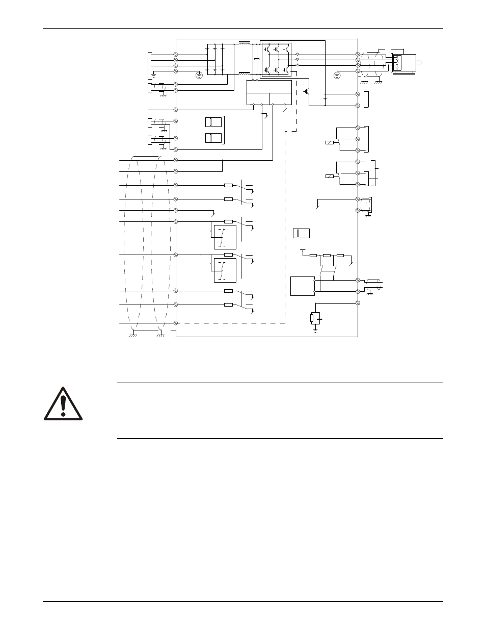
Figure 5: Basic electrical connection
Motor connection
WARNING:
INDUCED VOLTAGE. Run output motor cables from multiple frequency converters
separately. Induced voltage from output motor cables run together can charge
equipment capacitors even with the equipment turned off and locked out. Failure to run
output motor cables separately could result in death or serious injury.
Be sure the following are adhered to:
• For maximum wire sizes see Power-dependent Specifications.
• Comply with local and national electrical codes
• Motor wiring knockouts or access panels are provided at the base of IP21 and higher
(NEMA 1/12) units
• Do not install power factor correction capacitors between the frequency converter
and the motor
• Do not wire a starting or pole-changing device between the frequency converter and
the motor
• Connect the 3–phase motor wiring to terminals 96 (U), 97 (V), and 98 (W)
• Ground the cable in accordance with grounding instructions provided
• Torque terminals in accordance with the informations provided in Connection
tightening torques.
• Follow motor manufacturer wiring requirements
Electrical Installation
20
Aquavar
®
Intelligent Pump Controller INSTRUCTION MANUAL