Serial communication, Common terminal wiring configurations – Xylem IM255 AQUAVAR Intelligent Pump Controller User Manual
Page 35
1
Min. 6 AWG or 16 mm
2
2
Equalizing cable
Serial communication
RS-485 is two-wire bus interface compatible with multi-drop network topology. For
example, nodes can be connected as a bus, or via drop cables from a common trunk line.
A total of 32 nodes can be connected to one network segment. Repeaters divide network
segments. Note that each repeater functions as a node within the segment in which it is
installed. Each node connected within a given network must have a unique node address,
across all segments. Terminate each segment at both ends, using either the termination
switch (BUS TER./S801) of the frequency converters or a biased termination resistor
network. Always use screened twisted pair (STP) cable for bus cabling, and always follow
good common installation practice.
Low-impedence ground (earth) connection of the screen at every node is important,
including at high frequencies. Thus, connect a large surface of the screen to ground
(earth) , for example with a cable clamp or a conductive cable gland. It may be necessary
to apply potential-equalizing cables to maintain the same ground (earth) potential
throughout the network. Particularly in installations with long cables.
To prevent impedence mismatch, always use the same type of cable throughout the entire
network. When connecting a motor to the frequency converter, always use screened
motor cable.
Table 3: Cable information
Cable
Screened twisted pair (STP)
Impedence
120 Ω
Max. cable length [m]
1200 including drop lines
500 station-to-station
Common terminal wiring configurations
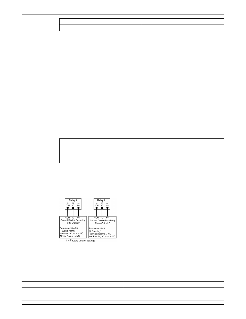
Relay wiring
Each controller has two programmable form C relay outputs. The relay terminals are
located in various locations on the controller depending on the frame size. NOTE: Relay
functions can be enabled using the Start-Up Genie.
Figure 18: Relay terminal wiring
Table 4: Relay terminal ratings
Programmable relay outputs
2
Relay 01 Terminal number
1–3 (break), 1–2 (make)
Maximum terminal load (AC-1)
1
on 1–3 (NC), 1–2 (NO) (Resistive load) 240 V AC, 2A
Maximum terminal load (AC-15)
1
(Inductive load @ cosφ 0.4)
240 V AC, 0.2A
Maximum terminal load (DC-1)
1
on 1–2 (NO), 1–3 (NC) (Resistive load) 60 V DC, 1A
Maximum terminal load (DC-13)
1
(Inductive load)
24 V DC, 0.1A
Electrical Installation
Aquavar
®
Intelligent Pump Controller INSTRUCTION MANUAL
33