Warning and alarm definitions – Xylem IM255 AQUAVAR Intelligent Pump Controller User Manual
Page 110
Warning and alarm definitions
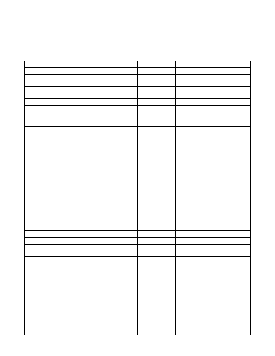
The following table defines whether a warning is issued before an alarm,
and whether the alarm trips the unit or trip locks the unit.
Table 30: Alarm/Warning code list
Number
Description
Warning
Alarm/Trip
Alarm/Trip Lock
Parameter Reference
1
10 volts low
X
2
Sensor Fault
(X)
(X)
6–01 Sensor Fault
Timeout Function
4
Input phase loss
(X)
(X)
(X)
14–12 Function at
Input Imbalance
5
DC link voltage high
X
6
DC link voltage low
X
7
DC overvoltage
X
X
8
DC undervoltage
X
X
9
Inverter overloaded
X
X
10
Motor ETR over-
temperature
(X)
(X)
1–90 Motor Thermal
Protection
11
Motor thermistor over
temperature
(X)
(X)
1–90 Motor Thermal
Protection
12
Torque limit
X
X
13
Over current
X
X
X
14
Ground/Earth fault
X
X
15
Hardware mismatch
X
X
16
Short Circuit
X
X
17
Control word timeout (X)
(X)
8–04 Control Word
Timeout Function
18
Start Failed
X
1–77 Compressor Start
Mar Speed [RPM], 1–
79 Compressor Start
Max Time to Trip, 1–03
Torque Characteristics
23
Internal fan fault
X
24
External fan fault
X
14–53 Fan Monitor
25
Brake resistor short-
circuited
X
26
Brake resistor power
limit
(X)
(X)
2–13 Brake Power
Monitoring
27
Brake chopper short-
circuited
X
X
28
Brake check
(X)
(X)
2–15 Brake Check
29
Drive over
temperature
X
X
X
30
Motor phase U
missing
(X)
(X)
(X)
4–58 Missing Motor
Phase Function
31
Motor phase V
missing
(X)
(X)
(X)
4–58 Missing Motor
Phase Function
32
Motor phase W
missing
(X)
(X)
(X)
4–58 Missing Motor
Phase Function
Warnings and alarms
108
Aquavar
®
Intelligent Pump Controller INSTRUCTION MANUAL