Xylem IM255 AQUAVAR Intelligent Pump Controller User Manual
Page 37
Protect Alarm to prevent nuisance tripping. When the input is disconnected from the 24V
supply, the delay timer will start. If the input remains disconnected for the time indicated
in [22-00] Pump Protect Delay, the controller stops the motor and issues Alarm 60 Pump
Protect. If a Pump Protect Alarm is issued, the controller will attempt to restart if the
[14-20] Reset Mode parameter and the [14-21] Automatic Restart Time parameter are set
to allow automatic restarting. To prevent an automatic restart set the [14-20] Reset Mode
to Manual Reset. Note that the [14-20] Reset Mode parameter affects all other Alarms that
are not listed as a Trip Lock Alarm. Refer to the Warnings/Alarm Messages section for
details.
NOTE: This function can be enabled using the Start-Up Genie.
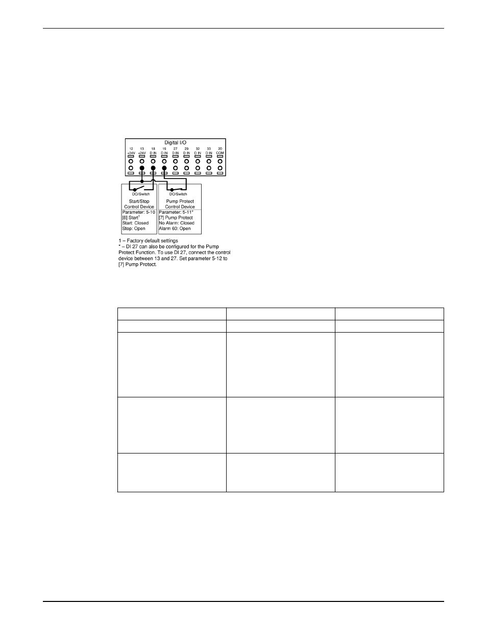
Figure 20: Connections for adding Pump Protect
Table 5: Parameter settings for enabling a Pump Protect Alarm on DI19
Parameter number
Parameter description
Set to
5–11*
Terminal 19 Digital Input
Pump Protect
22–00
Pump Protect Delay
Set to the desired delay time. If set to
10 seconds, the Pump Protect Alarm
will be issued 10 seconds after the
input is disconnected from 24V. The
input must remain disconnected for
the entire delay time for the alarm to
be issued.
14–20
Reset Mode
Set to the desired number of
automatic resets. If a fault occurs
more than this setting, a manual
reset is required. Set to Manual Reset
if no resets are allowed. Default
setting is: Automatic reset x 3.
14–21
Automatic Restart Time
This is the time between when an
alarm/warning is issued and when
the controller attempts the next
restart. Default setting is 30 seconds.
* To configure DI 27, set 5–12 to Pump Protect.
Configuring an additional transducer feedback
An additional transducer can be added to the system to work with closed loop control or
for external monitoring. The additional transducer can be either a voltage output or
current output transducer. The additional transducer can be added to the unused analog
input (AI 53 or AI 54). The wiring below shows the required connections for an additional
transducer on AI 54.
Electrical Installation
Aquavar
®
Intelligent Pump Controller INSTRUCTION MANUAL
35