Bell & Gossett 193 TECHNOVAR VARIABLE SPEED PUMP CONTROLLER AND INTEGRATED AJUSTABLE FREQUENCY DRIVE User Manual
Page 58
Operating Instruction
58
3. Set the synchronous threshold (f
0
+ 2-3 Hz)
4. Set the synchronous offset to 1-2 Hz
(depending on the pump curve and operating point).
To leave the submenu press the longer than 3 sec. to change to
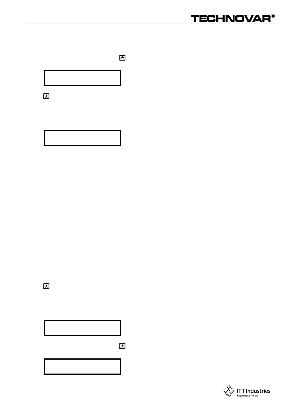
S U B M E N U
Synch. Control
Press on the Technovar to change to
10.22.7 Pump status indication
PUMP – SEQUENCE
Adr1 disabled
Shows the status of the individual drives
- for follow-up pump switching
- (adjustable from addresses 1 to 4, address 5 is
reserved for an external control device)
- for master function / take over of master function if
there is any malfunction of the master drive.
- Information concerning the actual sequential status
of each pump.
The following diagnosis parameters can be also be read in this display window:
hold Px Pump is stopped (control released)
run Px Pump is running (control released)
stop Px Pump is stopped, because f< start frequency of the previous
pump
Disabled Converter not ready to start (no release)
Error Converter error
Fault Polling failure (RS-485)
(interface connection wrong or not connected)
Detected Polling successful (RS-485)
AdrX * “*” -> Address of the pump that is being read
Press on the Technovar to change to
10.22.8 Error Signals for Data Bus Interruptions
BUSARBIT-DIAG.
0
Counts the number of synchronising attempts over
the RS-485 interface.
To leave the submenu press the longer than 3 sec. to change to
S U B M E N U
Seq. Control