Bell & Gossett 193 TECHNOVAR VARIABLE SPEED PUMP CONTROLLER AND INTEGRATED AJUSTABLE FREQUENCY DRIVE User Manual
Page 22
Operating Instruction
22
Connect the included 2-wire.black cable with the fan-board (Picture 6) an take it upside to
the internal fan. Then place the cable beside the internal fan and fix it with the two cable-
connectors which are shown in Picture 7.
Next put the cable through the hole at the front of the Technovar and pull it below the
control card at the bottom (Picture 8).
On the frontside of the control-card is an connector for plug in the control cable what you see
in Picture 9.
Mounting the fan on the Technovar
Place the Technovar at the AC-fan that you can see the LCD-Display at the front and the
pieces for the wallmounted component are on the side (Picture 11).
Then put the fan-cable through the hole and fix it with the included cable gland from picture
12. Look that the cable goes between the heat sink and isn´t fixed from it (Picture 12).
Connect the fan-cable at the connection clamps U2, V2, W2 on the fan board and screw the
GND-cable with the GND screw (Picture 10).
Next take the four long screws M6x25mm and the lock washers (see picture 1/A and B) and fix
the Technovar on the AC-fan with the nuts you can see in picture 2/E.
At least put the wall mounted component (Picture 13) behind the Technovar and fix this 2
components with the four short screws M6x12mm and the lock washers (see Picture 1/C and
D) what you see in picture 14.
!!
PLEASE NOTE:
The fan is only running with the TECHNOVAR (Run Signal).
Connect the fan cable so that the fan can blow from the carrier-
sheed through the heat sink.
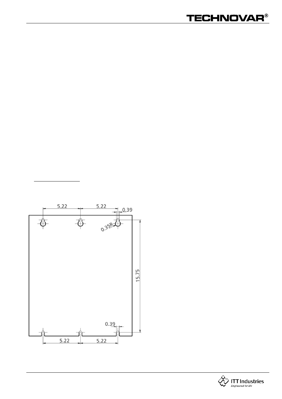
Dimension drawing