Bell & Gossett 193 TECHNOVAR VARIABLE SPEED PUMP CONTROLLER AND INTEGRATED AJUSTABLE FREQUENCY DRIVE User Manual
Page 21
Operating Instruction
21
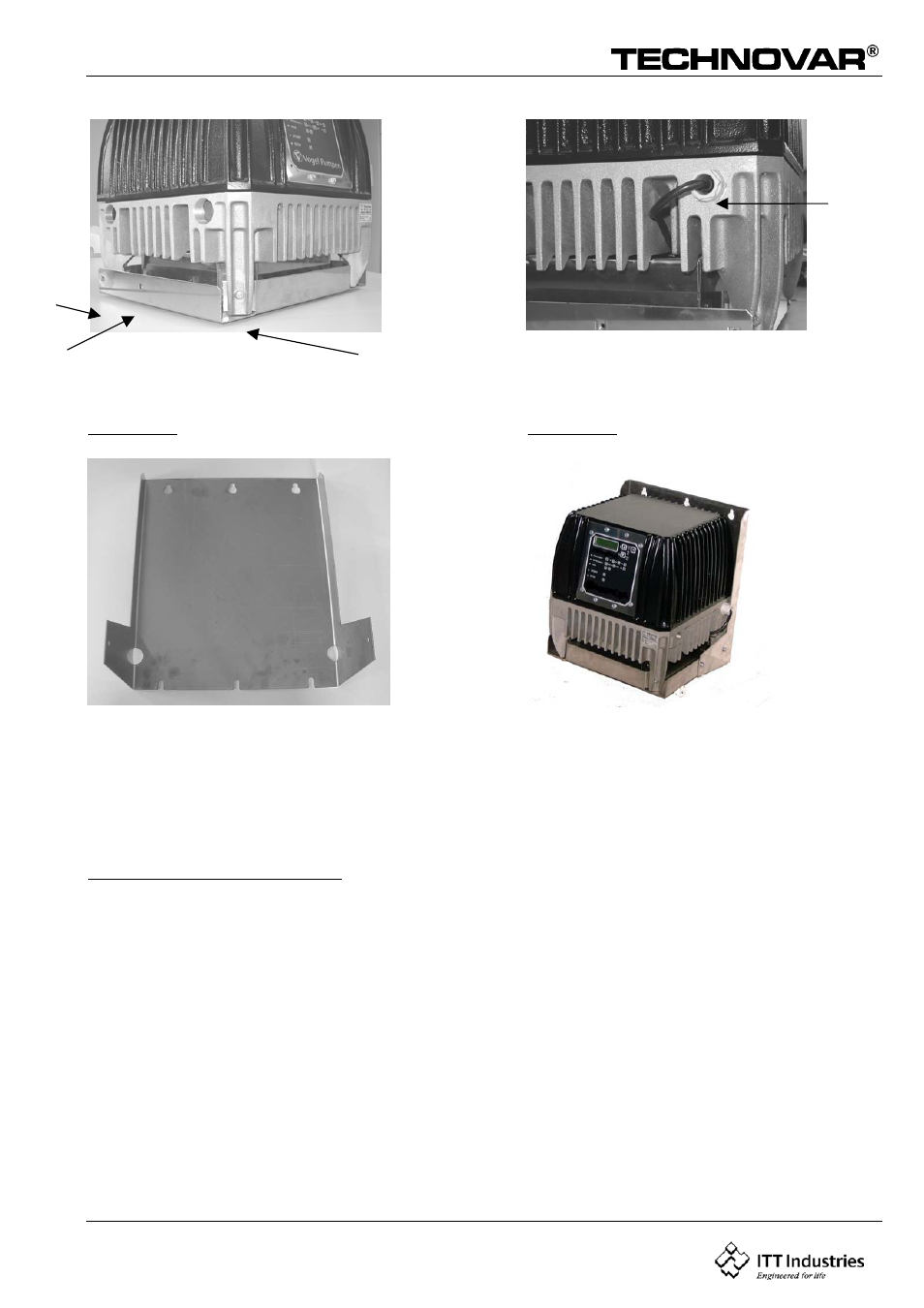
Picture 11
Picture 12
12
Picture 13
Picture 14
Mounting the wallmounted kit on the Technovar
BEFORE REMOVING THE FREQUENCY INVERTER COVER THE SYSTEM MUST BE DIS-CONNECTED
FROM THE POWER SUPPLY. AFTER SWITCHING OFF THE POWER SUPPLY WAIT AT LEAST 5
MINUTES BEFORE STARTING WORK ON OR IN THE TECHNOVAR DRIVE HEAD.
Mounting the fan-board
Loosen the 4 main screws from the Technovar cover and also the 8 screws holding the
control-card.
Then remove the Technovar cover carefully. (Take care with the control-card and the GND-
Cable.)
Picture 3 shows you the fan-board (incl. the 3 fuses 1A/500V- picture 3/G) that you can fix
with the 3 plastic-distances in the 3 holes which are made for. (Picture 4)
The power supply for the fan-board comes from the connections L1, L2, L3 on the primary-
side from the rectifier-board.
Please fasten the connection screw as well and connect the right cable with the right
connection
Compare the cable number and the connection number. (Picture 5).
Connecting the control-cable
- 10 001 247 R3 TechnoForce Package System (36 pages)
- 10 001 265R5 TechnoForce Pump Controller (76 pages)
- 10-001-275 XLS Integrated Pump Controller (57 pages)
- 10-001-278 XLS Integrated Pump Controller (44 pages)
- 176R0649C Technologic 502 Series Pump Controller (74 pages)
- 210667C Z-4 (2 pages)
- 210668B Z-4B (6 pages)
- 211013D PSE 800 M Low Water Cut-off (20 pages)
- MM 217L Series 150S and 157S Low Water Cut-Offs/Pump Controllers (12 pages)
- Iron & Bronze Booster Pumps Series 100 (4 pages)
- P2001487 Technologic Pump Controller (93 pages)
- P2000642B i-ALERT Condition Monitor (18 pages)
- P80922A Zone Trol Pump Controller ZT-1X (4 pages)
- P80925B Zone Trol Zone Pump Controller ZT-2 (6 pages)
- S11574C Heat Transfer Package with Air Separation (8 pages)
- S11865A TECHNOLOGIC 1100 SERIES PUMP CONTROLLER (4 pages)
- 70E Multiple Pump & Control Pressure Booster Systems (28 pages)
- S12260 R4 Genuine Bell & Gossett Replacement Seal Kit (1 page)
- S12596B Technologic 350 Pump Controller (24 pages)
- S13213A MiniBooster Pumping Package (10 pages)
- S13641B Technologic 5500 Series Pump Controller (38 pages)
- S13654B Technologic 5500 Series Pump Controller (31 pages)
- S14141B 70X Multiple Pump Pressure Booster Systems (12 pages)
- S14333 Technologic 5500 Series ZoneSav Controller (38 pages)
- S14334B Technologic 5500 Series Variable Primary Pump and Valve Controller (54 pages)
- S14362C Glycol Make-up Unit (10 pages)
- S14367B Technologic Constant Speed Pump Controller (44 pages)
- 6 71 075 003A Autocirc Instant Hot Water Pump Models e3-4/BDPQC (8 pages)
- 6 71 075 110A The ecocirc auto/vario Series Pumps (4 pages)
- 6 71 075 111A Autocirc Instant Hot Water Pump Model ecocirc 23 5 ACT (8 pages)
- 6 71 075 114A Series e3 SC Solar Circulators (6 pages)
- 6 71 075 115A LS Condensate Removal Pump (6 pages)
- 6 71 075 141B ecocirc wireless Potable Hot Water Recirculation Kit (28 pages)
- A 00 091 365A Series e3 4/e3 6 Instant Hot Water Recirculating Systems (6 pages)
- A 00 091 391A Automatic Plug-In Timer for e³-4/e³-6 Circulators (2 pages)
- A91590B DB-3/4″ Differential By-Pass Valve 3/4″ x 3/4″ NPT Male Connections Operational Limits (2 pages)
- A91591 Number 98 High Capacity Air Vent 1/2″ Female NPT Connection Operational Limits (3 pages)
- AC8584D Series HSCS Base Mounted Centrifugal Pumps (32 pages)
- IM207R00 Series 3530 (24 pages)
- IM228R04 e-SV (64 pages)
- MN 414 AC Submersible Pump Motors (16 pages)
- P0002560 Wireless Module and RS-485 Module (8 pages)
- P15758C Replacing the Bearing Frame Assembly or Pump Shaft (5 pages)
- P15776H Little Red Booster Pumps (4 pages)