Free space for wallmounting mounting instructions – Bell & Gossett 193 TECHNOVAR VARIABLE SPEED PUMP CONTROLLER AND INTEGRATED AJUSTABLE FREQUENCY DRIVE User Manual
Page 17
Operating Instruction
17
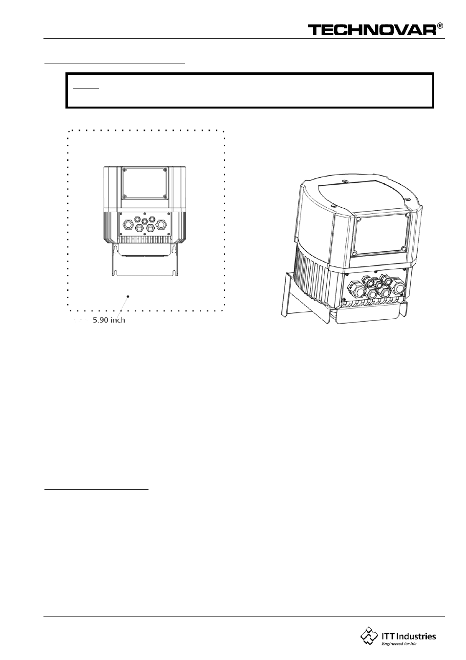
Free space for wallmounting
MOUNTING INSTRUCTIONS
BEFORE REMOVING THE FREQUENCY INVERTER COVER THE SYSTEM MUST BE DIS-CONNECTED
FROM THE POWER SUPPLY. AFTER SWITCHING OFF THE POWER SUPPLY WAIT AT LEAST 5
MINUTES BEFORE STARTING WORK ON OR IN THE TECHNOVAR DRIVE HEAD.
Mounting the mounting plate on the HV 2.1-3.11
Place the heat sink of the Technovar on the mounting plate and fix them together by using the 4 self
threading M3x8mm respective M4x15mm screws (Picture 3).
Connecting the fan-cable
Remove the 3 screws holding the top cover of the Technovar and lift it carefully (picture 4).
NOTE: Take care with the connection cable to the display and the Ground-cable!
Left the cover aside.
Mount the included cable gland (Picture 2D/2E) on the cover plate and put the cable through the cable
gland. (Picture 7).
Connect the fan cable with the Molex connector (Picture 5) and then plug it into the right connection
on the control card (Picture 6).
NOTE: Take care of at the correct polarity:
Red cable – plus pole
Black cable – minus pole
Fix the length of the cable inside the Technovar and tighten the cable gland to have ensure the IP55
class of protection.
Note: You have to leave a free space in front of the Technovar for
configuration and for dismounting the cover.
free space required for cooling and mounting