0 5.0 branch circuit monitoring system (bcms), Branch circuit monitoring system (bcms), Bcms components – GE Industrial Solutions GE ZENITH SERIES MDU User Manual
Page 33: Acquisition module
5.0
5.0 Branch Circuit Monitoring System (BCMS)
Your
the Plus version as an
An installed BCMS
currents. The total currents a
Plus
calculations.
Parameters are displayed locally on the
5.1.
GE
601
Plano, TX 75074
Branch Circuit Monitoring System (BCMS)
Your
the Plus version as an
An installed BCMS
currents. The total currents a
Plus option
calculations.
Parameters are displayed locally on the
5.1.
Calibration and Set
Panelboard #2 Even
Panelboard #2 Odd
Panelboard #1 Even
GE Z
ENITH
601 S
Plano, TX 75074
Branch Circuit Monitoring System (BCMS)
Your MDU
the Plus version as an
An installed BCMS
currents. The total currents a
option
calculations.
Parameters are displayed locally on the
5.1.
Calibration and Set
Ribbon cable connection for
Panelboard #2 Even
Ribbon cable connection for
Panelboard #2 Odd
Ribbon cable connection for
Panelboard #1 Even
Ribbon cable connection for
Panelboard #1 Odd
ENITH
S
HILOH
Plano, TX 75074
Branch Circuit Monitoring System (BCMS)
MDU may be equipped with
the Plus version as an
An installed BCMS
currents. The total currents a
option,
calculations.
Parameters are displayed locally on the
BCMS Components
5.1.1.
Calibration and Set
Ribbon cable connection for
Panelboard #2 Even
Ribbon cable connection for
Panelboard #2 Odd
Ribbon cable connection for
Panelboard #1 Even
Ribbon cable connection for
Panelboard #1 Odd
ENITH
C
ONTROLS
HILOH
R
OAD
Plano, TX 75074
Branch Circuit Monitoring System (BCMS)
may be equipped with
the Plus version as an
An installed BCMS
currents. The total currents a
in addition to current monitoring,
calculations.
Parameters are displayed locally on the
BCMS Components
5.1.1.
Calibration and Set
Ribbon cable connection for
Panelboard #2 Even
Ribbon cable connection for
Panelboard #2 Odd
Ribbon cable connection for
Panelboard #1 Even
Ribbon cable connection for
Panelboard #1 Odd
24 VAC Connection
ONTROLS
OAD
Plano, TX 75074
Branch Circuit Monitoring System (BCMS)
may be equipped with
the Plus version as an
An installed BCMS
currents. The total currents a
in addition to current monitoring,
Parameters are displayed locally on the
BCMS Components
5.1.1.
Calibration and Set-
Ribbon cable connection for
Panelboard #2 Even
Ribbon cable connection for
Panelboard #2 Odd
Ribbon cable connection for
Panelboard #1 Even
Ribbon cable connection for
Panelboard #1 Odd
24 VAC Connection
ONTROLS
Branch Circuit Monitoring System (BCMS)
may be equipped with
the Plus version as an
An installed BCMS Basic
currents. The total currents a
in addition to current monitoring,
Parameters are displayed locally on the
BCMS Components
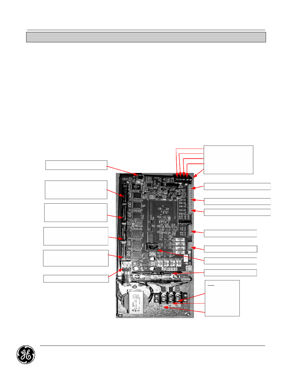
Acquisition Module
The Acquisition module consists of a fuse, small control transformer and a printed circuit
board (Figure 1 in Appendix A) mounted on a plate. There can be up to 4 CT modules
connected to this board, for a to
digital points. There are also eight terminals for Power CT’s to enable the BCMS to monitor
total current. It sends this information out via ModBus RTU to the local display or customer
supplie
-up Port (J16)
Ribbon cable connection for
Panelboard #2 Even (2,
(J5
Ribbon cable connection for
Panelboard #2 Odd (1, 3, 5…)
(J4
Ribbon cable connection for
Panelboard #1 Even
(J3
Ribbon cable connection for
Panelboard #1 Odd
(J2
24 VAC Connection
Branch Circuit Monitoring System (BCMS)
may be equipped with
the Plus version as an added feature to the
Basic option renders the capability to
currents. The total currents a
in addition to current monitoring,
Parameters are displayed locally on the
BCMS Components
Acquisition Module
The Acquisition module consists of a fuse, small control transformer and a printed circuit
board (Figure 1 in Appendix A) mounted on a plate. There can be up to 4 CT modules
connected to this board, for a to
digital points. There are also eight terminals for Power CT’s to enable the BCMS to monitor
total current. It sends this information out via ModBus RTU to the local display or customer
supplie
up Port (J16)
Ribbon cable connection for
(2, 4, 6…)
(J5—PB2B)
Ribbon cable connection for
(1, 3, 5…)
(J4—PB2A)
Ribbon cable connection for
(2, 4, 6…)
(J3—
Ribbon cable connection for
(1, 3, 5…)
(J2—
24 VAC Connection
Branch Circuit Monitoring System (BCMS)
may be equipped with
added feature to the
option renders the capability to
currents. The total currents a
in addition to current monitoring,
Parameters are displayed locally on the
BCMS Components
Acquisition Module
The Acquisition module consists of a fuse, small control transformer and a printed circuit
board (Figure 1 in Appendix A) mounted on a plate. There can be up to 4 CT modules
connected to this board, for a to
digital points. There are also eight terminals for Power CT’s to enable the BCMS to monitor
total current. It sends this information out via ModBus RTU to the local display or customer
supplied monitoring system.
up Port (J16)
Ribbon cable connection for
4, 6…)
PB2B)
Ribbon cable connection for
(1, 3, 5…)
PB2A)
Ribbon cable connection for
(2, 4, 6…)
—PB1B)
Ribbon cable connection for
(1, 3, 5…)
—PB1A)
24 VAC Connection
Branch Circuit Monitoring System (BCMS)
may be equipped with
added feature to the
option renders the capability to
currents. The total currents are a summation of the branch circuit breakers on each panel board
in addition to current monitoring,
Parameters are displayed locally on the
BCMS Components
Acquisition Module
The Acquisition module consists of a fuse, small control transformer and a printed circuit
board (Figure 1 in Appendix A) mounted on a plate. There can be up to 4 CT modules
connected to this board, for a to
digital points. There are also eight terminals for Power CT’s to enable the BCMS to monitor
total current. It sends this information out via ModBus RTU to the local display or customer
d monitoring system.
up Port (J16)
Ribbon cable connection for
4, 6…)
PB2B)
Ribbon cable connection for
(1, 3, 5…)
PB2A)
Ribbon cable connection for
(2, 4, 6…)
PB1B)
Ribbon cable connection for
(1, 3, 5…)
PB1A)
24 VAC Connection
Branch Circuit Monitoring System (BCMS)
may be equipped with GE
added feature to the
option renders the capability to
re a summation of the branch circuit breakers on each panel board
in addition to current monitoring,
Parameters are displayed locally on the
BCMS Components
Acquisition Module
The Acquisition module consists of a fuse, small control transformer and a printed circuit
board (Figure 1 in Appendix A) mounted on a plate. There can be up to 4 CT modules
connected to this board, for a to
digital points. There are also eight terminals for Power CT’s to enable the BCMS to monitor
total current. It sends this information out via ModBus RTU to the local display or customer
d monitoring system.
Branch Circuit Monitoring System (BCMS)
GE’s Branch
added feature to the
option renders the capability to
re a summation of the branch circuit breakers on each panel board
in addition to current monitoring,
Parameters are displayed locally on the
BCMS Components
Acquisition Module
The Acquisition module consists of a fuse, small control transformer and a printed circuit
board (Figure 1 in Appendix A) mounted on a plate. There can be up to 4 CT modules
connected to this board, for a to
digital points. There are also eight terminals for Power CT’s to enable the BCMS to monitor
total current. It sends this information out via ModBus RTU to the local display or customer
d monitoring system.
Branch Circuit Monitoring System (BCMS)
Branch
added feature to the
option renders the capability to
re a summation of the branch circuit breakers on each panel board
in addition to current monitoring,
Parameters are displayed locally on the GE Zenith Series
Acquisition Module
The Acquisition module consists of a fuse, small control transformer and a printed circuit
board (Figure 1 in Appendix A) mounted on a plate. There can be up to 4 CT modules
connected to this board, for a to
digital points. There are also eight terminals for Power CT’s to enable the BCMS to monitor
total current. It sends this information out via ModBus RTU to the local display or customer
d monitoring system.
MDU Owner’
Branch Circuit Monitoring System (BCMS)
Branch
added feature to the MDU
option renders the capability to
re a summation of the branch circuit breakers on each panel board
in addition to current monitoring,
GE Zenith Series
Acquisition Module
The Acquisition module consists of a fuse, small control transformer and a printed circuit
board (Figure 1 in Appendix A) mounted on a plate. There can be up to 4 CT modules
connected to this board, for a to
digital points. There are also eight terminals for Power CT’s to enable the BCMS to monitor
total current. It sends this information out via ModBus RTU to the local display or customer
d monitoring system.
MDU Owner’
Branch Circuit Monitoring System (BCMS)
Branch Circuit Monitoring System
MDU system
option renders the capability to
re a summation of the branch circuit breakers on each panel board
in addition to current monitoring, measures and monitors source voltages
GE Zenith Series
The Acquisition module consists of a fuse, small control transformer and a printed circuit
board (Figure 1 in Appendix A) mounted on a plate. There can be up to 4 CT modules
connected to this board, for a to
digital points. There are also eight terminals for Power CT’s to enable the BCMS to monitor
total current. It sends this information out via ModBus RTU to the local display or customer
d monitoring system.
MDU Owner’
Branch Circuit Monitoring System (BCMS)
Circuit Monitoring System
system
option renders the capability to
re a summation of the branch circuit breakers on each panel board
measures and monitors source voltages
GE Zenith Series
The Acquisition module consists of a fuse, small control transformer and a printed circuit
board (Figure 1 in Appendix A) mounted on a plate. There can be up to 4 CT modules
connected to this board, for a total of 84 CT’s. There are terminals for six voltages and four
digital points. There are also eight terminals for Power CT’s to enable the BCMS to monitor
total current. It sends this information out via ModBus RTU to the local display or customer
MDU Owner’
Branch Circuit Monitoring System (BCMS)
Circuit Monitoring System
system
option renders the capability to
re a summation of the branch circuit breakers on each panel board
measures and monitors source voltages
GE Zenith Series
The Acquisition module consists of a fuse, small control transformer and a printed circuit
board (Figure 1 in Appendix A) mounted on a plate. There can be up to 4 CT modules
tal of 84 CT’s. There are terminals for six voltages and four
digital points. There are also eight terminals for Power CT’s to enable the BCMS to monitor
total current. It sends this information out via ModBus RTU to the local display or customer
MDU Owner’s Manual
Branch Circuit Monitoring System (BCMS)
Circuit Monitoring System
system.
option renders the capability to measure
re a summation of the branch circuit breakers on each panel board
measures and monitors source voltages
GE Zenith Series MDU
The Acquisition module consists of a fuse, small control transformer and a printed circuit
board (Figure 1 in Appendix A) mounted on a plate. There can be up to 4 CT modules
tal of 84 CT’s. There are terminals for six voltages and four
digital points. There are also eight terminals for Power CT’s to enable the BCMS to monitor
total current. It sends this information out via ModBus RTU to the local display or customer
s Manual
Branch Circuit Monitoring System (BCMS)
Circuit Monitoring System
measure
re a summation of the branch circuit breakers on each panel board
measures and monitors source voltages
MDU Monitor.
The Acquisition module consists of a fuse, small control transformer and a printed circuit
board (Figure 1 in Appendix A) mounted on a plate. There can be up to 4 CT modules
tal of 84 CT’s. There are terminals for six voltages and four
digital points. There are also eight terminals for Power CT’s to enable the BCMS to monitor
total current. It sends this information out via ModBus RTU to the local display or customer
s Manual
Branch Circuit Monitoring System (BCMS)
Circuit Monitoring System
measure and monitor panel board and/or sub
re a summation of the branch circuit breakers on each panel board
measures and monitors source voltages
Monitor.
The Acquisition module consists of a fuse, small control transformer and a printed circuit
board (Figure 1 in Appendix A) mounted on a plate. There can be up to 4 CT modules
tal of 84 CT’s. There are terminals for six voltages and four
digital points. There are also eight terminals for Power CT’s to enable the BCMS to monitor
total current. It sends this information out via ModBus RTU to the local display or customer
Branch Circuit Monitoring System (BCMS)
s Manual
Branch Circuit Monitoring System (BCMS)
Circuit Monitoring System
and monitor panel board and/or sub
re a summation of the branch circuit breakers on each panel board
measures and monitors source voltages
Monitor.
The Acquisition module consists of a fuse, small control transformer and a printed circuit
board (Figure 1 in Appendix A) mounted on a plate. There can be up to 4 CT modules
tal of 84 CT’s. There are terminals for six voltages and four
digital points. There are also eight terminals for Power CT’s to enable the BCMS to monitor
total current. It sends this information out via ModBus RTU to the local display or customer
Branch Circuit Monitoring System (BCMS)
Circuit Monitoring System (BCMS
and monitor panel board and/or sub
re a summation of the branch circuit breakers on each panel board
measures and monitors source voltages
Monitor.
The Acquisition module consists of a fuse, small control transformer and a printed circuit
board (Figure 1 in Appendix A) mounted on a plate. There can be up to 4 CT modules
tal of 84 CT’s. There are terminals for six voltages and four
digital points. There are also eight terminals for Power CT’s to enable the BCMS to monitor
total current. It sends this information out via ModBus RTU to the local display or customer
Branch Circuit Monitoring System (BCMS)
BCMS
and monitor panel board and/or sub
re a summation of the branch circuit breakers on each panel board
measures and monitors source voltages
The Acquisition module consists of a fuse, small control transformer and a printed circuit
board (Figure 1 in Appendix A) mounted on a plate. There can be up to 4 CT modules
tal of 84 CT’s. There are terminals for six voltages and four
digital points. There are also eight terminals for Power CT’s to enable the BCMS to monitor
total current. It sends this information out via ModBus RTU to the local display or customer
Branch Circuit Monitoring System (BCMS)
BCMS) in either the
and monitor panel board and/or sub
re a summation of the branch circuit breakers on each panel board
measures and monitors source voltages
The Acquisition module consists of a fuse, small control transformer and a printed circuit
board (Figure 1 in Appendix A) mounted on a plate. There can be up to 4 CT modules
tal of 84 CT’s. There are terminals for six voltages and four
digital points. There are also eight terminals for Power CT’s to enable the BCMS to monitor
total current. It sends this information out via ModBus RTU to the local display or customer
Branch Circuit Monitoring System (BCMS)
) in either the
and monitor panel board and/or sub
re a summation of the branch circuit breakers on each panel board
measures and monitors source voltages
The Acquisition module consists of a fuse, small control transformer and a printed circuit
board (Figure 1 in Appendix A) mounted on a plate. There can be up to 4 CT modules
tal of 84 CT’s. There are terminals for six voltages and four
digital points. There are also eight terminals for Power CT’s to enable the BCMS to monitor
total current. It sends this information out via ModBus RTU to the local display or customer
TB1
Ground Input
Neutral Input
120 VAC Input
Source 1 Voltage (J9)
Ret
RX
RX+ (TX+)
TX
TX+
Source 2 Voltage (J10)
Source Breaker Closed (J1)
Neutral and Grd. CT Currents (J11)
Panel board 2 CT Currents (J13)
Panel board 1 CT Currents (J12)
Factory Programming Port
Branch Circuit Monitoring System (BCMS)
) in either the
and monitor panel board and/or sub
re a summation of the branch circuit breakers on each panel board
measures and monitors source voltages
The Acquisition module consists of a fuse, small control transformer and a printed circuit
board (Figure 1 in Appendix A) mounted on a plate. There can be up to 4 CT modules
tal of 84 CT’s. There are terminals for six voltages and four
digital points. There are also eight terminals for Power CT’s to enable the BCMS to monitor
total current. It sends this information out via ModBus RTU to the local display or customer
TB1
Ground Input
Neutral Input
120 VAC Input
Source 1 Voltage (J9)
Ret
RX- (TX
RX+ (TX+)
TX-
TX+
Source 2 Voltage (J10)
Source Breaker Closed (J1)
Neutral and Grd. CT Currents (J11)
Panel board 2 CT Currents (J13)
Panel board 1 CT Currents (J12)
Factory Programming Port
Branch Circuit Monitoring System (BCMS)
) in either the
and monitor panel board and/or sub
re a summation of the branch circuit breakers on each panel board
measures and monitors source voltages and determines
The Acquisition module consists of a fuse, small control transformer and a printed circuit
board (Figure 1 in Appendix A) mounted on a plate. There can be up to 4 CT modules
tal of 84 CT’s. There are terminals for six voltages and four
digital points. There are also eight terminals for Power CT’s to enable the BCMS to monitor
total current. It sends this information out via ModBus RTU to the local display or customer
Ground Input
Neutral Input
120 VAC Input
Source 1 Voltage (J9)
(TX-)
RX+ (TX+)
Source 2 Voltage (J10)
Source Breaker Closed (J1)
Neutral and Grd. CT Currents (J11)
Panel board 2 CT Currents (J13)
Panel board 1 CT Currents (J12)
Factory Programming Port
Branch Circuit Monitoring System (BCMS)
) in either the Basic
and monitor panel board and/or sub
re a summation of the branch circuit breakers on each panel board
and determines
The Acquisition module consists of a fuse, small control transformer and a printed circuit
board (Figure 1 in Appendix A) mounted on a plate. There can be up to 4 CT modules
tal of 84 CT’s. There are terminals for six voltages and four
digital points. There are also eight terminals for Power CT’s to enable the BCMS to monitor
total current. It sends this information out via ModBus RTU to the local display or customer
Ground Input
Neutral Input
120 VAC Input
Source 1 Voltage (J9)
)
RX+ (TX+)
Source 2 Voltage (J10)
Source Breaker Closed (J1)
Neutral and Grd. CT Currents (J11)
Panel board 2 CT Currents (J13)
Panel board 1 CT Currents (J12)
Factory Programming Port
Branch Circuit Monitoring System (BCMS)
Basic
and monitor panel board and/or sub
re a summation of the branch circuit breakers on each panel board.
and determines
The Acquisition module consists of a fuse, small control transformer and a printed circuit
board (Figure 1 in Appendix A) mounted on a plate. There can be up to 4 CT modules
tal of 84 CT’s. There are terminals for six voltages and four
digital points. There are also eight terminals for Power CT’s to enable the BCMS to monitor
total current. It sends this information out via ModBus RTU to the local display or customer
Ground Input
Neutral Input
120 VAC Input
Source 1 Voltage (J9)
RS485
(J14)
Source 2 Voltage (J10)
Source Breaker Closed (J1)
Neutral and Grd. CT Currents (J11)
Panel board 2 CT Currents (J13)
Panel board 1 CT Currents (J12)
Factory Programming Port
Branch Circuit Monitoring System (BCMS)
January 2013
Page
Basic version or
and monitor panel board and/or sub
. The BCMS
and determines
The Acquisition module consists of a fuse, small control transformer and a printed circuit
board (Figure 1 in Appendix A) mounted on a plate. There can be up to 4 CT modules
tal of 84 CT’s. There are terminals for six voltages and four
digital points. There are also eight terminals for Power CT’s to enable the BCMS to monitor
total current. It sends this information out via ModBus RTU to the local display or customer
Source 1 Voltage (J9)
RS485
(J14)
Source 2 Voltage (J10)
Source Breaker Closed (J1)
Neutral and Grd. CT Currents (J11)
Panel board 2 CT Currents (J13)
Panel board 1 CT Currents (J12)
Factory Programming Port
Branch Circuit Monitoring System (BCMS)
January 2013
Page
version or
and monitor panel board and/or sub-feed
The BCMS
and determines power
The Acquisition module consists of a fuse, small control transformer and a printed circuit
board (Figure 1 in Appendix A) mounted on a plate. There can be up to 4 CT modules
tal of 84 CT’s. There are terminals for six voltages and four
digital points. There are also eight terminals for Power CT’s to enable the BCMS to monitor
total current. It sends this information out via ModBus RTU to the local display or customer
RS485
Source 2 Voltage (J10)
Source Breaker Closed (J1)
Neutral and Grd. CT Currents (J11)
Panel board 2 CT Currents (J13)
Panel board 1 CT Currents (J12)
Factory Programming Port
Branch Circuit Monitoring System (BCMS)
January 2013
Page 33
version or
feed
The BCMS
power
The Acquisition module consists of a fuse, small control transformer and a printed circuit
board (Figure 1 in Appendix A) mounted on a plate. There can be up to 4 CT modules
tal of 84 CT’s. There are terminals for six voltages and four
digital points. There are also eight terminals for Power CT’s to enable the BCMS to monitor
total current. It sends this information out via ModBus RTU to the local display or customer
RS485
Source Breaker Closed (J1)
Neutral and Grd. CT Currents (J11)
Panel board 2 CT Currents (J13)
Panel board 1 CT Currents (J12)
Factory Programming Port
Branch Circuit Monitoring System (BCMS)
January 2013
33
version or
feed
The BCMS
power
The Acquisition module consists of a fuse, small control transformer and a printed circuit
tal of 84 CT’s. There are terminals for six voltages and four
digital points. There are also eight terminals for Power CT’s to enable the BCMS to monitor
total current. It sends this information out via ModBus RTU to the local display or customer
Neutral and Grd. CT Currents (J11)
Panel board 2 CT Currents (J13)
Panel board 1 CT Currents (J12)
Branch Circuit Monitoring System (BCMS)
tal of 84 CT’s. There are terminals for six voltages and four
Neutral and Grd. CT Currents (J11)