Internal wire sizing – GE Industrial Solutions GE ZENITH SERIES MDU User Manual
Page 12
Installation Procedures
GE Z
ENITH
C
ONTROLS
MDU Owner’s Manual
601 S
HILOH
R
OAD
January 2013
Plano, TX 75074
Page 12
3.3.
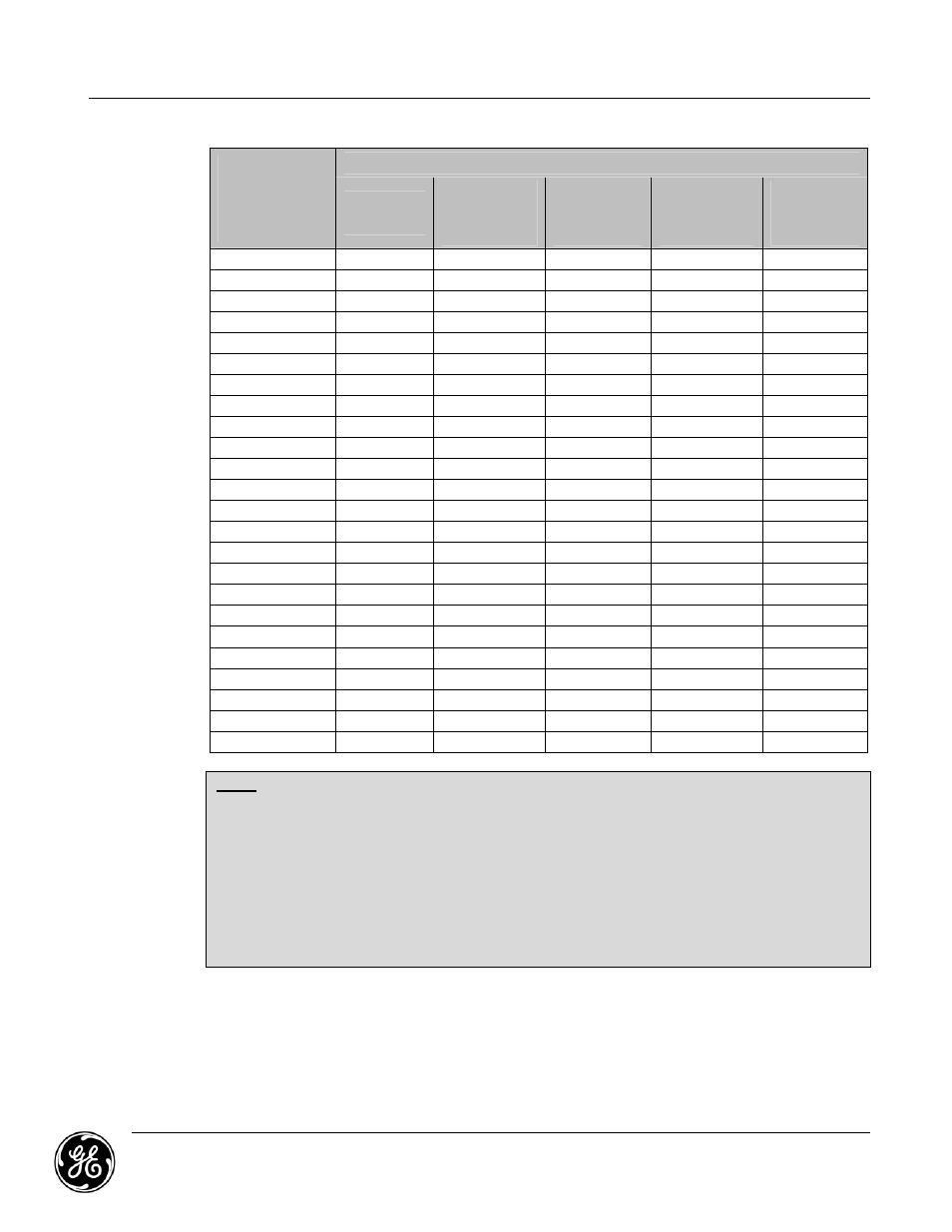
Internal Wire Sizing
Protective
Circuit Breaker
or Actual
Amperage
3,4
Internal Conductors
Phase Wire,
Single
1,3,4,6
Phase Wire,
Two
Parallel
1,3,4,6
Neutral
Wire,
Single
1,3,4,6
Neutral Wire,
Two
Parallel
1,3,4,6
Ground
Wire,
Single
1,3,4,6
25
#10
#14
#10
#12
#10
30
#10
#12
#8
#10
#10
40
#8
#10
#8
#10
#10
50
#8
#10
#6
#10
#10
60
#8
#8
#4
#8
#10
70
#8
#8
#3
#8
#8
80
#6
#8
#3
#8
#8
90
#6
#8
#2
#6
#8
100
#4
#8
#1
#6
#8
110
#4
#8
#1
#4
#6
125
#4
#8
1/0
#4
#6
150
#2
#6
2/0
#3
#6
175
#1
#6
3/0
#2
#6
200
1/0
#4
3/0
#1
#6
225
1/0
#4
4/0
1/0
#4
250
2/0
#3
250MCM
1/0
#4
300
3/0
#2
350MCM
2/0
#4
350
4/0
#1
400MCM
3/0
#3
400
250MCM
1/0
500MCM
4/0
#3
500
350MCM
2/0
750MCM
300MCM
#2
600
500MCM
3/0
1000MCM
400MCM
#1
700
700MCM
4/0
1500MCM
500MCM
1/0
800
800MCM
250MCM
N/A
700MCM
1/0
1000
1000MCM
350MCM
N/A
1000MCM
2/0
Notes:
1. Conductor ratings are based on NEC Table 310.17.
2. Deleted.
3. All wires must be UL listed.
4. Conductors must be separated for air circulation – not bundled
5. Parallel conductor lengths must be equal within 2% (e.g. two parallel conductors 10 feet
long must match in length within 2.4”).
6. For components like circuit breakers, the 75°C column in NEC Table 310.17 must be used.
7. For components like bus bars that allow 90°C connections, the 90°C column in NEC Table
310.17 can be used.