Installation guide, User interface for data configuration, Amp1h5 – GE Industrial Solutions AMP1H5 User Manual
Page 9
TM
AMP1H5
INSTALLATION GUIDE
ZL0115-0A
PAGE 9
©2013 For technical support please contact
01132
DET-785
our GE tech support team at 1-800-GE-1-STOP (1-800-431-7867)
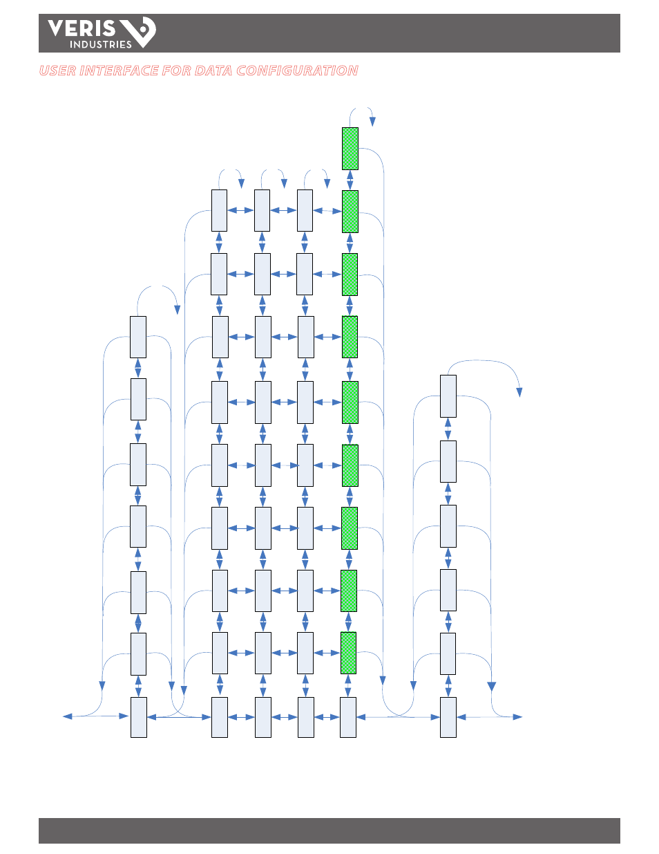
USER INTERFACE FOR DATA CONFIGURATION
_P
H
A
S
APHA
S
BPHA
S
CPHAS
3 A
3 VLL
3 VLN
3 KW
A A
A
VA
B
A
K
W
1, 2, o
r 3 Phase
Summary D
ata
Phase
A:
Al
l System
s
Phase
B
:
2
&
3
Phase
System
s
O
nl
y
Phase C
:
3
P
ha
se
S
ystems
Onl
y
A
VL
N
V
ol
ts
L
in
e-
Li
ne
(U
)
(Av
er
ag
e
of
Active
Phas
es)
A
m
ps
(A
)
(Av
er
age
of
Ac
tiv
e
P
has
es)
V
ol
ts
L
in
e-
N
eut
ra
l (
V)
(A
vera
ge
o
f Ac
tiv
e
Ph
as
es
)
To
ta
l R
ea
l
Po
w
er
(P
)
Po
wer
Fac
tor
(A
ve
rag
e
of
Active
P
ha
ses
)
3
KV
A
Tot
al
Ap
pa
ren
t
P
ow
er
(S
)
B A
B
VB
C
B
K
W
B
VL
N
C
A
C
VA
C
C
K
W
C V
LN
A
KV
A
B
KV
A
C KVA
A
P
F
3
P
F
B
P
F
C
P
F
3KVA
R
To
tal
R
ea
ct
ive
P
ow
er
(Q
)
AKVA
R
BKVA
R
CKVA
R
KVAR
h
K
VA
h
Acc
um
ul
ate
d
R
eac
tiv
e E
ne
rgy
(Q
h)
Accumula
te
d
Ap
pa
re
nt
E
ne
rg
y
(Sh
)
DEMND
D KW
P
re
sen
t
R
eal
P
ow
er
D
em
and
(P
)
M
K
W
M
KVA
R
M
KV
A
M
ax
im
um
Ap
pa
ren
t Po
w
er
D
em
and
(S
)
M
axim
um
R
ea
ct
ive
P
ow
er
D
em
an
d
(Q
)
M
axim
um
R
ea
l P
ow
er
D
em
an
d
(P
)
DKVA
R
P
rese
nt
Re
ac
tiv
e
Po
w
er
D
em
and
(Q
)
D
KV
A
P
res
en
t
A
ppa
re
nt
P
ow
er
D
em
an
d
(S
)
DEMND
Dem
and
>>>
S
cro
ll
When
Id
le
>
>>
To:
SE
TU
P
APHA
S
BPHA
S
CP
H
A
S
A
KW
h
3
KW
h
B
KW
h
C
KW
h
_P
H
A
S
HZ
Fr
eq
ue
nc
y
Accumula
te
d
R
ea
l E
ne
rg
y
ENRG
Y
To:
A
LE
RT
En
ergy
Ac
cu
m
ul
at
ors
and Co
unters
ENRG
Y
P
UL
S
1
Input Pu
ls
e
C
ou
nte
r
P
UL
S
2
P
ul
se
C
ou
nt
er
2
(not used on E50H2)
KWh
Acc
um
ul
ate
d
R
ea
l E
ne
rg
y
(P
h)