Installation guide, Amp1h5 – GE Industrial Solutions AMP1H5 User Manual
Page 18
TM
AMP1H5
INSTALLATION GUIDE
ZL0115-0A
PAGE 18
©2013 For technical support please contact
01132
DET-785
our GE tech support team at 1-800-GE-1-STOP (1-800-431-7867)
#
Name
Description R/W
NV
Units
Range
Factory
Default
Value
Additional information
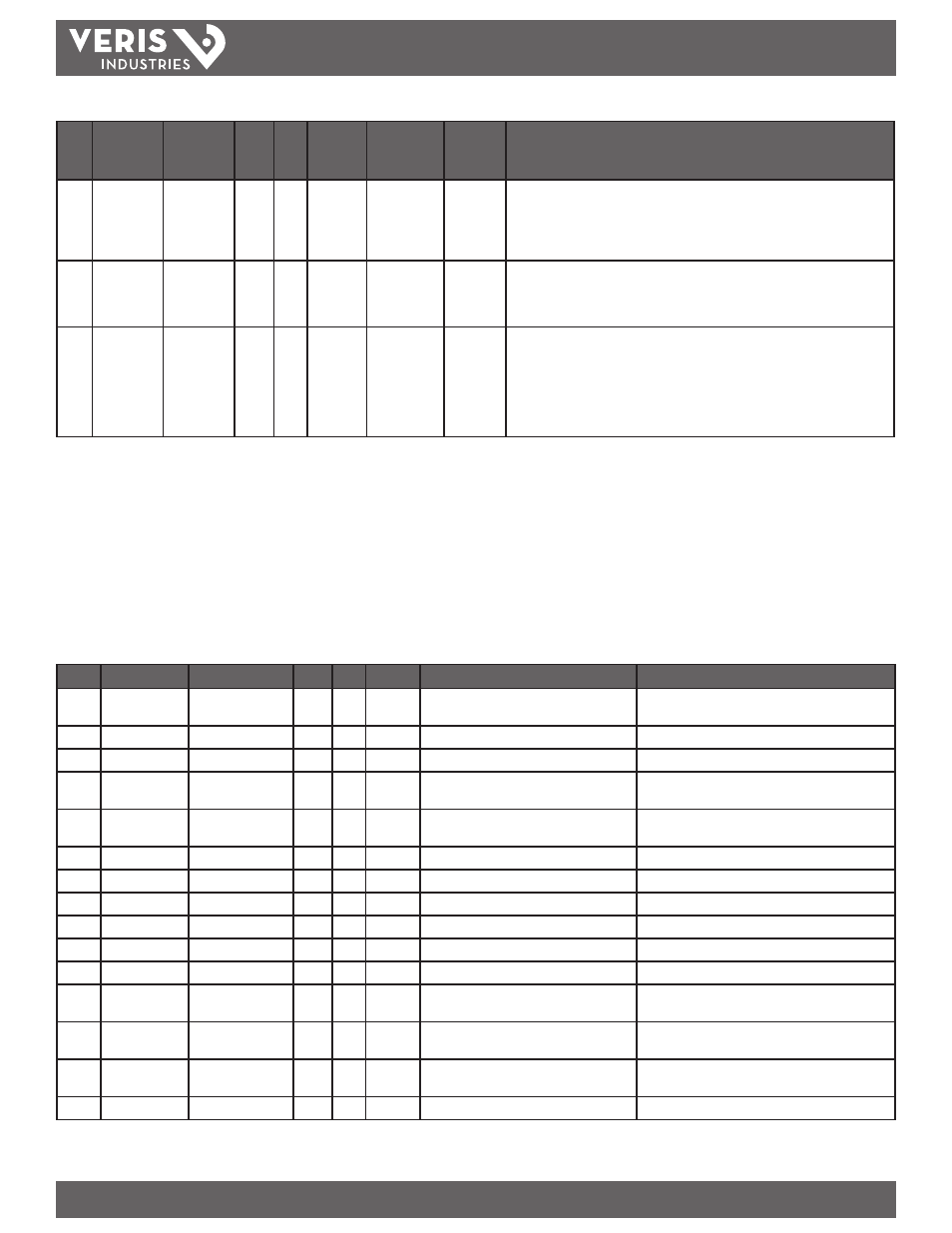
AV9
Phase_
Loss_
Imbalance_
Threshold
Phase Loss
Imbalance
Threshold
R/W
NV
Percent
1-99
25
Phase Loss Imbalance Threshold in Percent. Default is 25% phase to phase difference.
For a 3-phase Y (3 + N) system type (40 in object AV2), both Line to Neutral and Line
to Line voltages are tested. In a 3-phase ∆ System type (31 in object AV2), only Line
to Line voltages are examined. In a single split-phase (2 + N) system type (12 in
object AV2), only the line to neutral voltage are compared.
AV10 Subintervals Number of
Subintervals
Per Demand
Interval
R/W
NV
1-6
1
Number of Sub-Intervals per Demand Interval. Sets the number of sub-intervals that
make a single demand interval. For block demand, set this to 1. Default is 1. When
Sub-Interval Length (in object AV11) is set to 0 (sync-to-comms mode), the meter
ignores this value.
AV11 Subinterval_
Length
Subinterval
Length
R/W
NV
hundreths
of a
second
0,
10-32767
90000
Sub-Interval Length in hundredths of a second. For sync-to-comms mode, which
allows manual triggerring of demand intervals and the logging of another Trend_
Log record, set this value to 0 and write 21211 to the reset register (object AV1) each
time the sub-interval must be externally reset. Default is 90000 (15 minutes). This
variable is tied directly to the Log_Interval property of all three Trend_Log objects
(their value is always the same as this one). Changing any of these four properties
changes all of them.
Analog_Input Objects
Use the Present_Value property of the Analog_Input objects for all read-only numeric variables in the meter other than those used specifically for device configuration (in the
Device Object) or data logging (in the Trend_Log objects).
These objects support the Description and Reliability object properties and all required Analog_Input object properties. None of them are writable. The values that are not
instantaneous (i.e., Accumulated Energy, Max Demand, Pulse Input Counts) are non-volatile. They are not updated while control power is inactive, but their past values are
retained when power is restored.
For complete assurance, check the Reliabilty property for a No_Fault_Detected status before reading the Present_Value. If the line voltage or input frequency of the system
being monitored falls out of the supported range, the corresponding alert bits (BI1-BI7) are set and the reliability property of any values that cannot be accurately measured
under those conditions returns Unreliable_Other.
#
Object_Name
Description
R/W
NV
Units
Range
Additional information
AI1
Energy
Real Energy
Consumption
R
NV
kWh
0 - 3.4+E38
AI2
kW_Total
Total Real Power
R
kW
0 - Max_Power (AI45)
AI3
kVAR_Total
Total Reactive Power R
kVAR
0 - Max_Power (AI45)
AI4
kVA_Total
Total Apparent
Power
R
kVA
0 - Max_Power (AI45)
AI5
PF_Total
Total Power Factor
R
Power
Factor
0.00 - 1.00
1.00 for 100%
AI6
Volts_LL_Avg
Voltage L-L Average
R
Volts
AI7
Volts_LN_Avg
Voltage L-N Average
R
Volts
AI8
Current_Avg
Current Average
R
Amps
AI9
kW_A
Real Power Phase A
R
kW
0 - Max_Power (AI45)
AI10
kW_B
Real Power Phase B
R
kW
0 - Max_Power (AI45)
AI11
kW_C
Real Power Phase C
R
kW
0 - Max_Power (AI45)
AI12
PF_A
Power Factor
Phase A
R
Power
Factor
0.00 - 1.00
1.00 for 100%
AI13
PF_B
Power Factor Phase B R
Power
Factor
0.00 - 1.00
1.00 for 100%
AI14
PF_C
Power Factor Phase C R
Power
Factor
0.00 - 1.00
1.00 for 100%
AI15
Volts_AB
Votlage Phase A-B
R
Volts