Caution, Installation guide, Wiring – GE Industrial Solutions AMP1H5 User Manual
Page 4: Supported system types, Data outputs, Amp1h5
TM
AMP1H5
INSTALLATION GUIDE
ZL0115-0A
PAGE 4
©2013 For technical support please contact
01132
DET-785
our GE tech support team at 1-800-GE-1-STOP (1-800-431-7867)
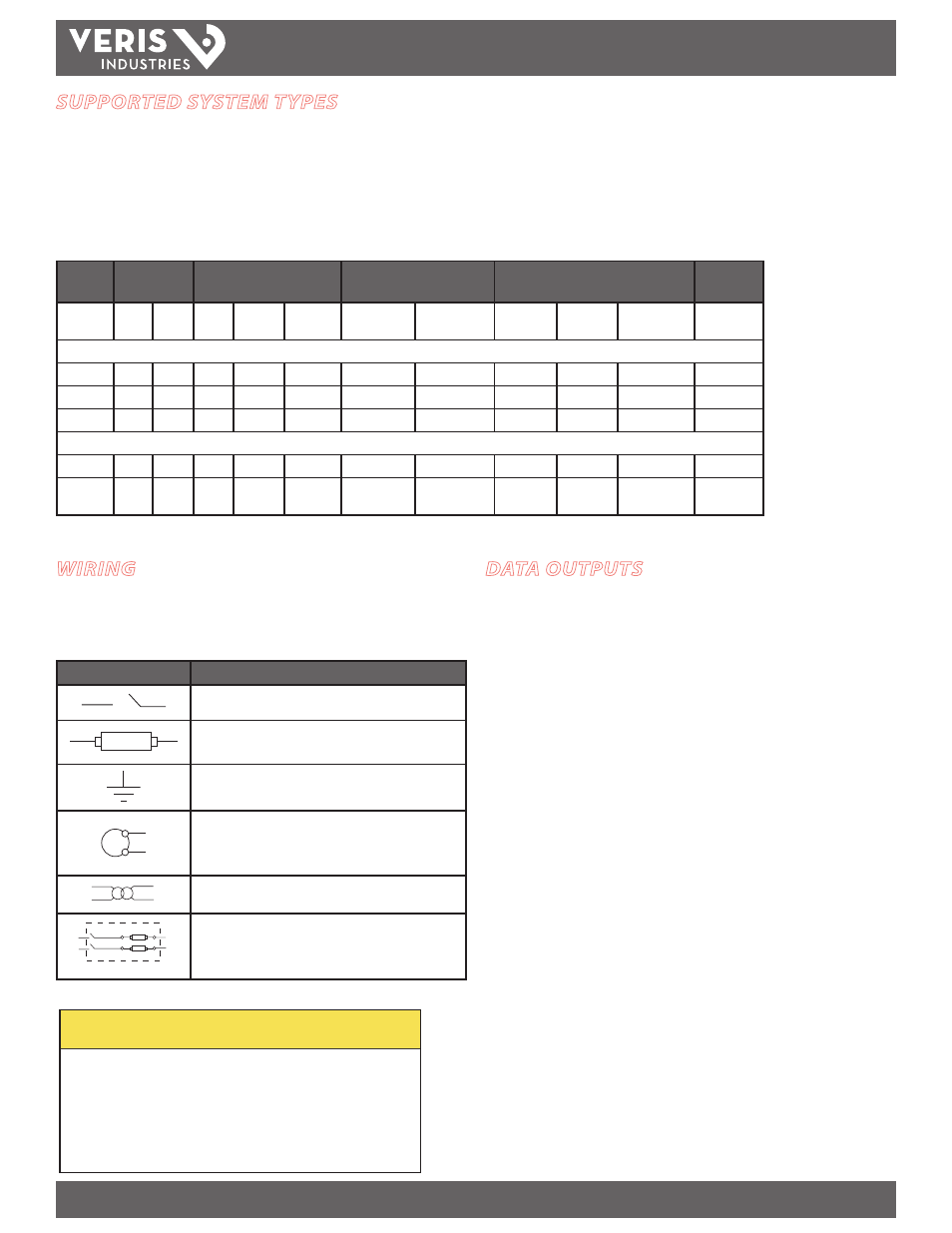
WIRING
To avoid distortion, use parallel wires for control power and voltage inputs.
The following symbols are used in the wiring diagrams on the following pages.
Symbol
Description
Voltage Disconnect Switch
Fuse (installer is responsible for ensuring compliance with
local requirements. No fuses are included with the meter.)
Earth ground
S2
S1
Current Transducer
Potential Transformer
Protection containing a voltage disconnect switch with a
fuse or disconnect circuit breaker. The protection device
must be rated for the available short-circuit current at the
connection point.
SUPPORTED SYSTEM TYPES
The AMP1H5 power meter has a number of different possible system wiring configurations (see Wiring Diagrams, page 5). To configure the meter, set the System Type via the
User Interface or by writing the Present_Value of AV2 with the System Type value in the table below. The System Type tells the meter which of its current and voltage inputs
are valid, which are to be ignored, and if neutral is connected. Setting the correct System Type prevents unwanted energy accumulation on unused inputs, selects the formula
to calculate the Theoretical Maximum System Power, and determines which phase loss algorithm is to be used. The phase loss algorithm is configured as a percent of the Line-
to-Line System Voltage (except when in System Type 10) and also calculates the expected Line to Neutral voltages for system types that have Neutral (12 & 40).
Values that are not valid in a particular System Type will display as “----” on the User Interface or as QNAN in the BACnet objects.
CTs
Voltage Connections
System Type
Phase Loss Measurements
Wiring
Diagram
Number
of wires
Qty
ID
Qty
ID
Type
BACnet object
AV2
User Interface:
SETUP>S SYS
VLL
VLN
Balance
Diagram
number
Single-Phase Wiring
2
1
A
2
A, N
L-N
10
1L + 1n
AN
1
2
1
A
2
A, B
L-L
11
2L
AB
2
3
2
A, B
3
A, B, N
L-L with N 12
2L + 1n
AB
AN, BN
AN-BN
3
Three-Phase Wiring
3
3
A, B, C 3
A, B, C
Delta
31
3L
AB, BC, CA
AB-BC-CA
4
4
3
A, B, C 4
A, B, C, N Grounded
Wye
40
3L + 1n
AB, BC, CA
AN, BN, CN AN-BN-CN &
AB-BC-CA
5, 6
CAUTION
RISK OF EQUIPMENT DAMAGE
• This product is designed only for use with 1V or 0.33V current
transducers (CTs).
• DO NOT USE CURRENT OUTPUT (e.g. 5A) CTs ON THIS PRODUCT.
• Failure to follow these instructions can result in overheating and
permanent equipment damage.
DATA OUTPUTS
Full Data Set (FDS):
Power (kW)
Energy (kWh)
Configurable for CT & PT ratios, system type, and passwords
Diagnostic alerts
Current: 3-phase average
Volts: 3-phase average
Current: by phase
Volts: by phase Line-Line and Line-Neutral
Power: Real, Reactive, and Apparent 3-phase total and per phase
Power Factor: 3-phase average and per phase
Frequency
Power Demand: Most Recent and Peak
Demand Configuration: Fixed, Rolling Block, and External Sync
Real Time Clock: uses BACnet Time Synchronization services
Data Logging (includes all FDS outputs, plus):
3 BACnet Log_Events: each buffer holds 5760 time-stamped 32-bit entries
(User configures which 3 data points are stored in these buffers)
User configurable logging interval
(When configured for a 15 minute interval, each buffer holds 60 days of
data)
Continuous and Single Shot logging modes: user selectable