Installation guide, Control power – GE Industrial Solutions AMP1H5 User Manual
Page 6
TM
AMP1H5
INSTALLATION GUIDE
ZL0115-0A
PAGE 6
©2013 For technical support please contact
01132
DET-785
our GE tech support team at 1-800-GE-1-STOP (1-800-431-7867)
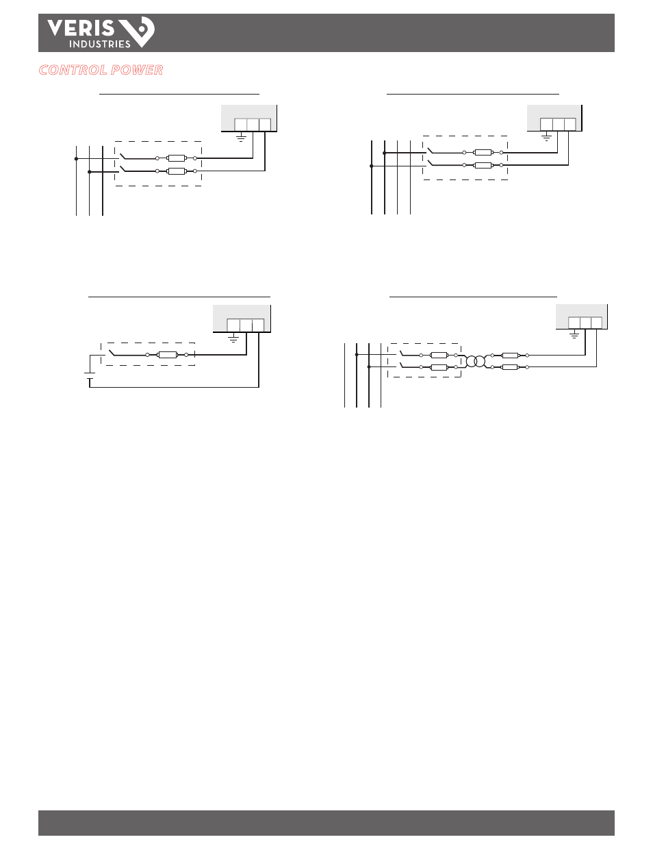
CONTROL POWER
Direct Connect Control Power (DC Control Power)
L1
N
L2 L3
1 2
G
L1
N
L2 L3
1 2
G
L1
1 2
G
L2 L3
Direct Connect Control Power (Line to Neutral)
Line to Neutral from 90 VAC to 347 VAC (UL) or 300 VAC (CE)
1 2
G
Control Power Transformer (CPT) Connection
Direct Connect Control Power (Line to Line)
Line to Line from 90 VAC to 600 VAC (UL) (520 VAC for CE). In UL installations the lines may be
floating (such as a delta). If any lines are tied to an earth (such as a corner grounded delta), see the
Line to Neutral installation limits. In CE compliant installations, the lines must be neutral (earth)
referenced at less than 300 VAC
L-N
The Control Power Transformer may be wired L-N or L-L. Output to meet meter input requirements
DC Control Power from 125 VDC to 300 VDC (UL and CE max.)
Fuse Recommendations:
Keep the fuses close to the power source (obey local and national code requirements).
For selecting fuses and circuit breakers, use the following criteria:
• Select current interrupt capacity based on the installation category and
fault current capability.
• Select over-current protection with a time delay.
• Use a voltage rating sufficient for the input voltage applied.
• Provide overcurrent protection and disconnecting means to protect
the wiring. For DC installations, provide external circuit protection.
Suggested: 0.5A, high-interrupt capability time delay fuses rated for DC
operation at or above the supply voltage.
• The earth connection is required for electromagnetic compatibility (EMC)
and is not a protective earth ground.