Installation guide, Installation, Product diagram – GE Industrial Solutions AMP1H5 User Manual
Page 3: Amp1h5, A. din rail mounting, B. screw mounting
TM
AMP1H5
INSTALLATION GUIDE
ZL0115-0A
PAGE 3
©2013 For technical support please contact
01132
DET-785
our GE tech support team at 1-800-GE-1-STOP (1-800-431-7867)
INSTALLATION
Disconnect power prior to installation.
Reinstall any covers that are displaced during the
installation before powering the unit.
Mount the meter in an appropriate electrical enclosure
near equipment to be monitored.
Do not install on the load side of a Variable Frequency Drive
(VFD), aka Variable Speed Drive (VSD) or Adjustable Frequency
Drive (AFD).
The meter can be mounted in two ways: on standard 35 mm DIN rail or screw-
mounted to the interior surface of the enclosure.
A. DIN Rail Mounting
1. Attach mounting clips to the underside of the housing by sliding them into the
slots from the inside. The stopping pegs must face the housing, and the outside
edge of the clip must be flush with the outside edge of the housing.
2. Snap the clips onto the DIN rail. See diagram of the underside of the housing
(below).
Clip flush with
outside edge
Snap onto
DIN rail
Insert clips from inside
3. To prevent horizontal shifting across the DIN rail, use two end stop clips.
B. Screw Mounting
1. Attach the mounting clips to the underside of the housing by sliding them into the
slots from the outside. The stopping pegs must face the housing, and the screw
hole must be exposed on the outside of the housing.
2. Use three #8 screws (not supplied) to mount the device to the inside of the
enclosure. See diagram of the underside of the housing (below).
Screw holes
exposed for
mounting
Insert clips from outside
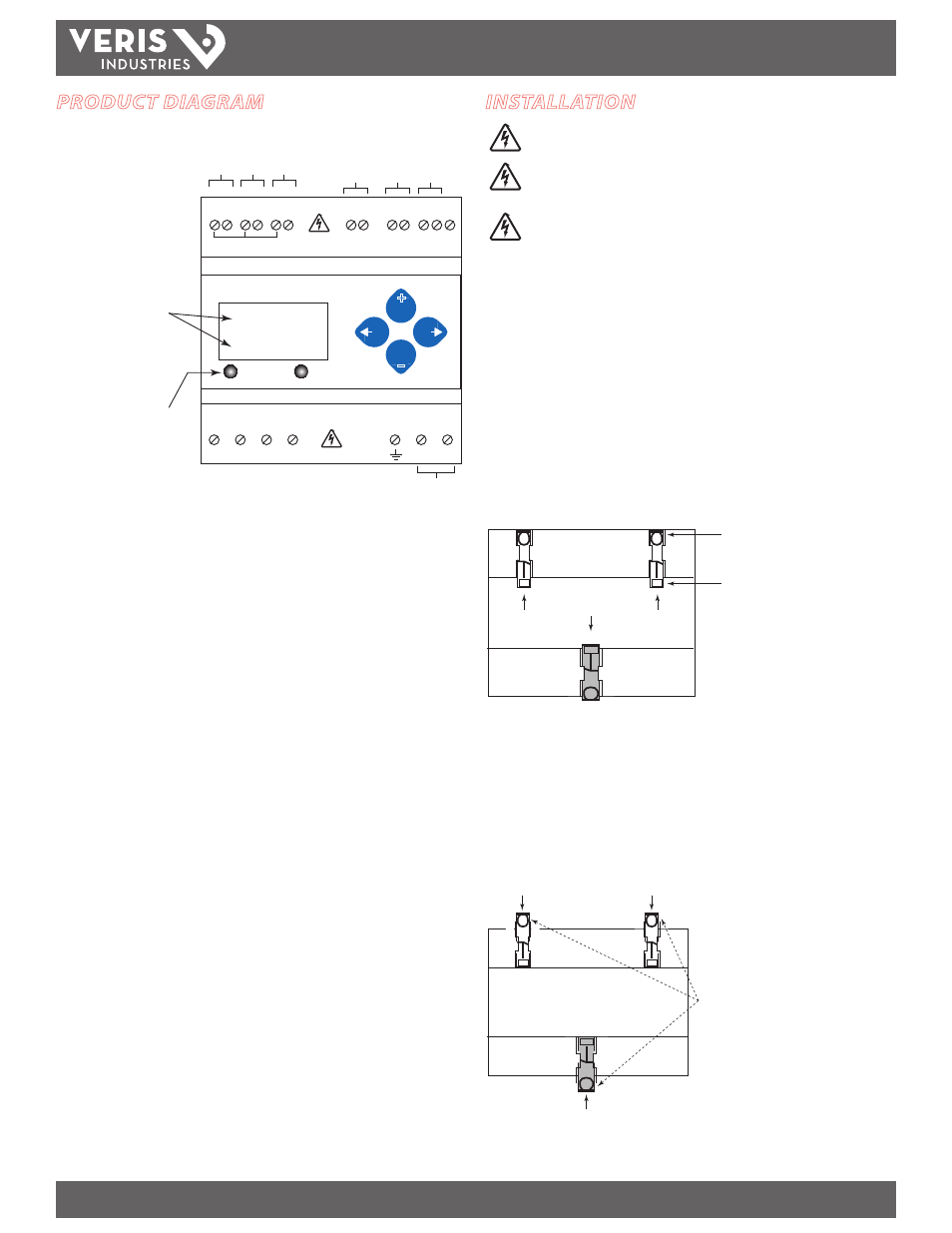
PRODUCT DIAGRAM
Alarm
Energy
Two 5-character rows
of display text.
Top row alphanumeric;
Bottom row numeric only
The red Alarm LED lights
when any of the 3 phase
voltages drop below the
selected threshold.
The green Energy LED lights
when the pulse 1 input
contacts are active or closed.
CONTROL POWER
0.1A 50/60 Hz
A
B
C
N
1
2
A
B
C
Pulse Inputs
1
2
+ - S
RS-485
Common - 1 or 1/3 VAC Input
-
+
-
+
-
+
IA
IB
IC
VA
VB
VC
Neutr
al
Ear
th
Con
trol
Po
we
r
UL: 90V
L-N
- 600V
L-L
CE: 90V
L-N
- 300V
L-N
VOLTAGE INPUTS
CAT III 50/60 Hz
+
–
Pulse Input 1
Pulse Input 2
BA
Cnet
Shield