Installation guide, Ui menu abbreviations defined, Pulse contact inputs – GE Industrial Solutions AMP1H5 User Manual
Page 8: Amp1h5
TM
AMP1H5
INSTALLATION GUIDE
ZL0115-0A
PAGE 8
©2013 For technical support please contact
01132
DET-785
our GE tech support team at 1-800-GE-1-STOP (1-800-431-7867)
UI MENU ABBREVIATIONS DEFINED
The user can set the display mode to IEC or IEEE notation in the SETUP menu.
Main Menu
IEC
IEEE
Description
D
D
Demand
MAX
M
Maximum Demand
P
W
Present Real Power
Q
VAR
Present Reactive Power
S
VA
Present Apparent Power
A
A
Amps
UAB, UBC, UAC VAB, VBC, VAC
Voltage Line to Line
V
VLN
Voltage Line to Neutral
PF
PF
Power Factor
U
VLL
Voltage Line to Line
HZ
HZ
Frequency
KSh
KVAh
Accumulated Apparent Energy
KQh
KVARh
Accumulated Reactive Energy
KPh
KWh
Accumulated Real Energy
PLOSS
PLOSS
Phase Loss
LOWPF
LOWPF
Low Power Factor Error
F ERR
F ERR
Frequency Error
I OVR
I OVR
Over Current
V OVR
V OVR
Over Voltage
PULSE
PULSE
kWh Pulse Output Overrun (configuration error)
_PHASE
_PHASE
Summary Data for 1, 2, or 3 active phases
ALERT
ALERT
Diagnostic Alert Status
INFO
INFO
Unit Information
MODEL
MODEL
Model Number
OS
OS
Operating System
RS
RS
Reset System
SN
SN
Serial Number
RESET
RESET
Reset Data
PASWD
PASWD
Enter Reset or Setup Password
ENERG
ENERG
Reset Energy Accumulators
DEMND
DEMND
Reset Demand Maximums
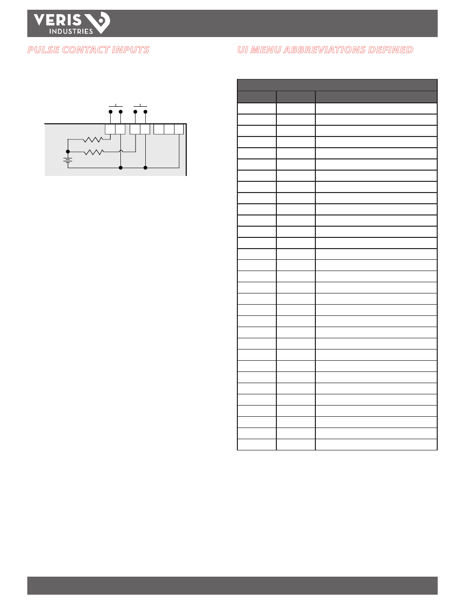
PULSE CONTACT INPUTS
The AMP1H5 has two inputs with pulse accumulators for solid state or mechanical
contacts in other sensors, such as water or gas flow meters. These inputs are isolated
from the measured circuits and referenced to the communication signal ground. Use
with contacts that do not require current to remove oxidation.
S
Comm
Output
+
~10 kΩ
Comm
Ground
4-10 VDC
nominal
Pulse Input
Contacts
Equivalent
Circuit