Reconnect a ups unit to redundant parallel system – GE Industrial Solutions TLE Series 225-500 User Manual User Manual
Page 80
Critical Power
Modifications reserved
Page 80/90
GE_UPS_USM_TLE_SUL_M22_M50_1US_V010.docx
User Manual TLE Series 225 - 500 UL S1
7.3.5 Reconnect a UPS unit to Redundant Parallel System
NOTE:
The Load is still powered by the other units supplying the parallel bus.
This UPS unit will be powered on and connected to the parallel bus in order to
share the Load with each other's.
The high speed bus cable connecting
J1A - J2A and J1B - J2B
in any case cannot be
connected or disconnected after the system has been powered on.
The bus terminals must be properly connected before powering the additional
unit.
If eBoost™ option is available, make sure that eBoost™ Operation Mode is disabled
before starting this procedure.
Open the front door, of the Unit to reconnect, and make sure that:
All the connections to the input/output terminals or bus bars of the UPS have been made correctly.
The protection panels are fastened in their correct position.
The switches Q1, Q2 and CB3 (option) are open (Pos. O) and the external Battery protections must
be open (Pos. O).
1. Switch-ON the Utility voltage, on the Unit to reconnect, from the input distribution (both
Rectifier and bypass if separated).
At this stage the Electronic Power Supply and Control Panel are switched ON and the Buzzer sounds.
Press “MUTE” key to reset Acoustical Alarm.
LED ALARM remains lit.
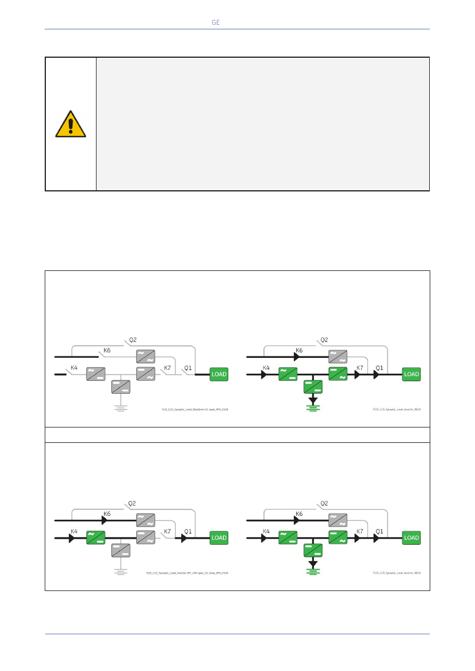
Synoptic diagram of the unit to reconnect
Synoptic diagram of other units
2. Close UPS output switch Q1 (Pos. I) on the Unit to reconnect.
Rectifier starts automatically.
LED 1 (Rectifier) blinking, indicates Soft-start.
At the end of Rectifier Soft-start the LED 1 (Rectifier) remains lit.
Synoptic diagram of the unit to reconnect
Synoptic diagram of other units
Continue ►