GE Industrial Solutions TLE Series 225-500 User Manual User Manual
Page 74
Critical Power
Modifications reserved
Page 74/90
GE_UPS_USM_TLE_SUL_M22_M50_1US_V010.docx
User Manual TLE Series 225 - 500 UL S1
7.3.2 Parallel UPS shut-down with load transfer on Manual Bypass Q2
NOTE !
If eBoost™ option is available, make sure that eBoost™ Operation Mode is disabled
before starting this procedure.
Initial status:
Load supplied from all Inverters of the Parallel
System.
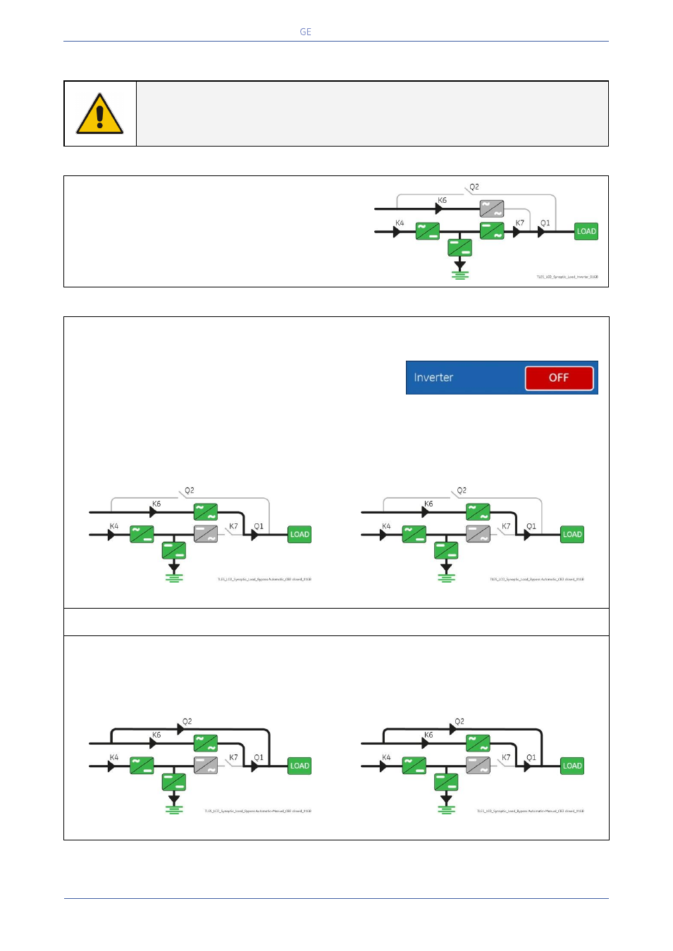
1. Disconnect the Inverter performing the “Inverter OFF” command on all Units.
1 - Perform the “Inverter OFF” command from the
screen: Commands 1 / Inverter / OFF.
2 - Repeat the “Inverter OFF” command from the
screen: Commands 1 / Inverter / OFF.
At no redundancy, the system will transfer to Utility supply. LED 2 (Inverter) is Off.
LED ALARM is lit.
The Synoptic Diagram, on all UPS units, must display the status “LOAD SUPPLIED BY AUTOMATIC BYPASS”.
Synoptic Diagram of first unit
Synoptic Diagram of other units
2. Close Manual Bypass switch Q2 (Pos. I) on all Units.
Load is now supplied from Utility in parallel from Automatic Bypass and Manual Bypass Q2 of all Units.
The Synoptic Diagram, on all UPS units, must display the status “LOAD SUPPLIED BY AUTOMATIC BYPASS
AND MANUAL BYPASS Q2”.
Synoptic Diagram of first unit
Synoptic Diagram of other units
Continue ►