GE Industrial Solutions TLE Series 225-500 User Manual User Manual
Page 25
Critical Power
Modifications reserved
Page 25/90
GE_UPS_USM_TLE_SUL_M22_M50_1US_V010.docx
User Manual TLE Series 225 - 500 UL S1
LED ALARM (yellow color)
It blinks when one or more alarm is activated. The internal Buzzer is ON.
The LED remains blinking (with the alarm condition still present) and the buzzer stops when the key
“MUTE” is pressed.
The LED ALARM is also lighted when the Load is not protected by UPS or in case Q1 is open.
LED STOP OPERATION (red color)
It warns about the imminent inverter stop (default parameter = 3 min.) and the consequent Load shut-
down as result of:
The battery is fully discharged and the Load cannot be transferred on Utility.
Overtemperature or overload condition (>125%) and the Load cannot be transferred on Utility.
Bypass
Data regarding Bypass.
See Section 6.2.
Rectifier
Data regarding Rectifier.
See Section 6.2.
Load output
Data regarding Load.
See Section 6.2.
Battery
Data regarding Battery.
See Section 6.2.
Green color: indicates battery charged.
Yellow color: indicates STOP OPERATION status.
Red color:
indicates low battery.
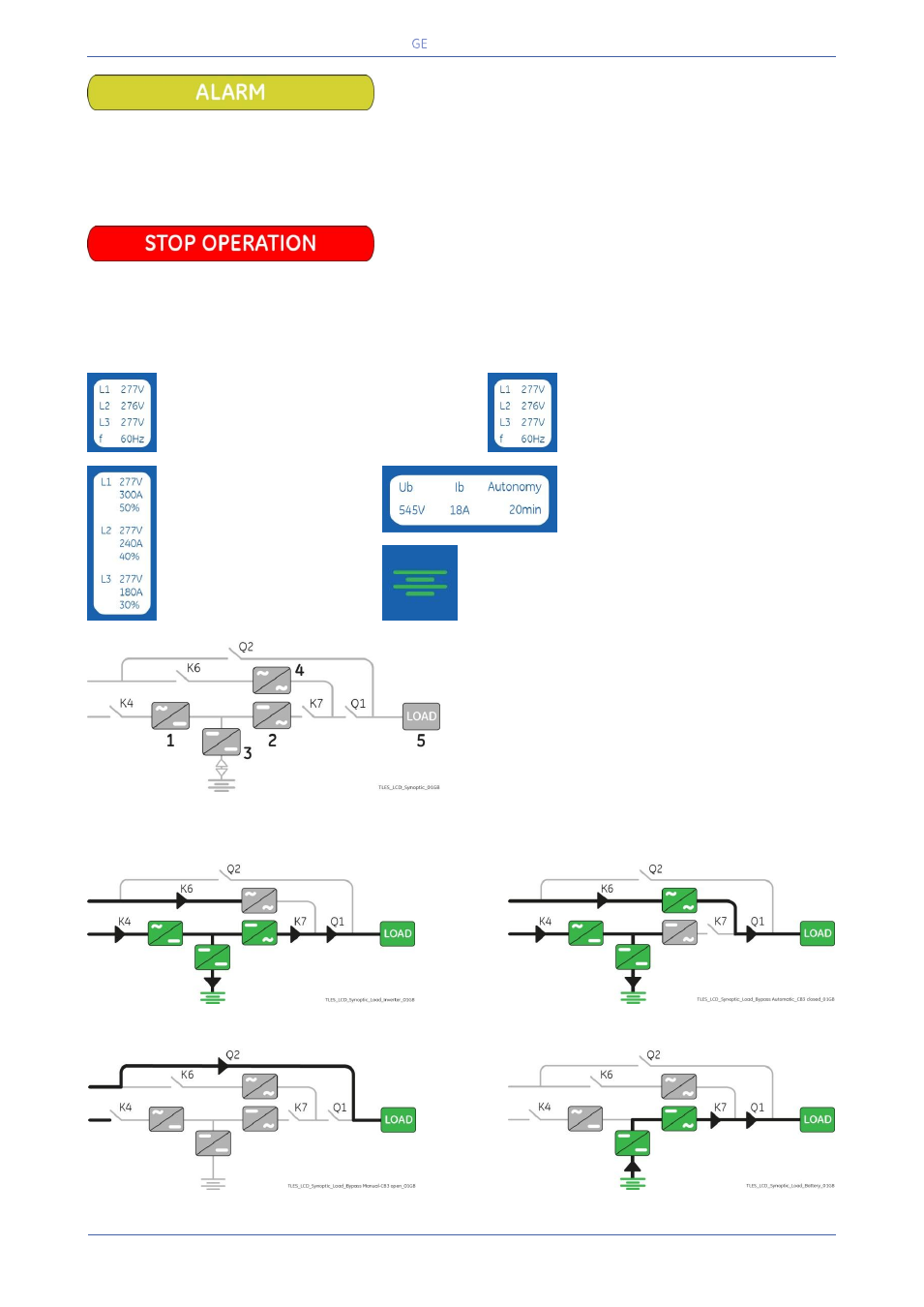
LEDs on Synoptic Diagram
LED 1
Rectifier
LED 2
Inverter
LED 3
Booster/Battery charger
LED 4
Automatic Bypass
LED 5
LOAD
Examples of typical scenarios in the Synoptic Diagram:
Load supplied by Inverter
Load supplied by Automatic Bypass
Load supplied by Manual Bypass Q2
Load supplied by Battery