GE Industrial Solutions TLE Series 225-500 User Manual User Manual
Page 68
Critical Power
Modifications reserved
Page 68/90
GE_UPS_USM_TLE_SUL_M22_M50_1US_V010.docx
User Manual TLE Series 225 - 500 UL S1
7.2.4 Restore to normal operation after EPO (Emergency Power Off)
NOTE !
Make sure the UPS to be status of the activation of EPO, i. e. Q1 CB3 (option) closed
and external Battery protection connected.
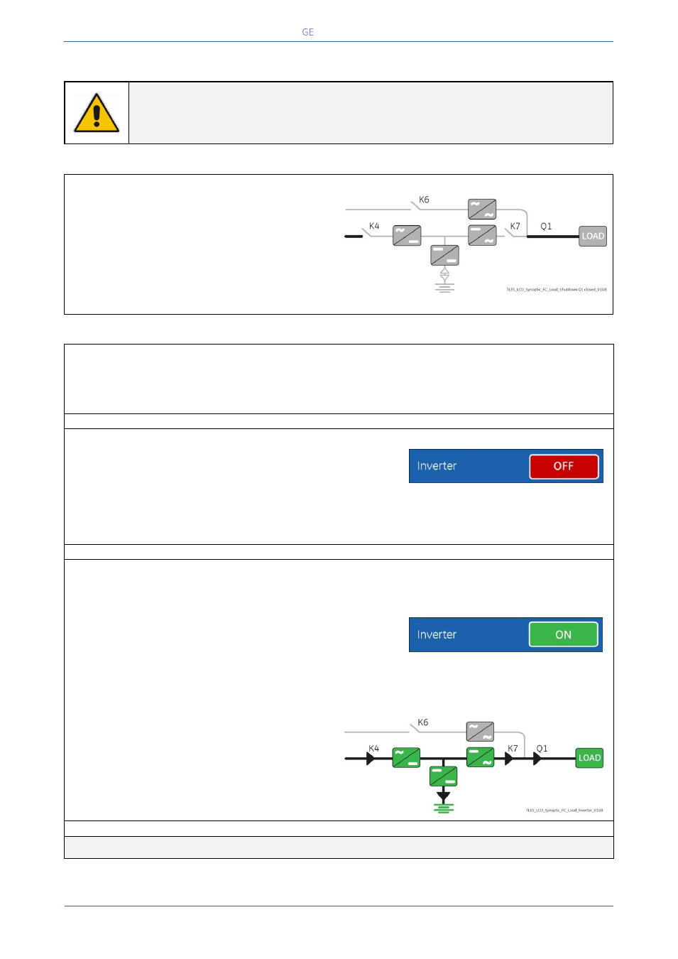
View of the Synoptic Diagram after
activation of EPO (Emergency Power Off) with
Utility available:
All Contactors are open.
Rectifier, Inverter, Booster/Battery charger
and Static-Switch shut-down.
LED ALARM is lit.
1. Reset the EPO (Emergency Power Off) button.
Press “MUTE” key to reset Alarm and Acoustical Alarm.
LED ALARM remains lit.
2. Perform the “Inverter OFF” command.
Perform the “Inverter OFF” command from
the screen: Commands 1 / Inverter / OFF.
Rectifier starts automatically.
LED 1 (Rectifier) blinking, indicates Soft-start.
At the end of Rectifier Soft-start the LED 1 (Rectifier) remains lit.
3. Insert the inverter performing the command “Inverter ON".
Before performing this procedure make sure that the LED 1 (Rectifier) and LED 3 (Booster/Battery
charger) are lit.
Perform the “Inverter ON” command from the screen:
Commands 1 / Inverter / ON.
Soft-start of Inverter indicated with blinking LED 2 (Inverter).
At the end of Soft-start the LED 2 (Inverter) remains lit.
LED ALARM turns Off and the LED LOAD PROTECTED must be lit.
The Synoptic Diagram must display the status
“LOAD SUPPLIED BY INVERTER”.
END OF PROCEDURE