GE Industrial Solutions TLE Series 225-500 User Manual User Manual
Page 65
Critical Power
Modifications reserved
Page 65/90
GE_UPS_USM_TLE_SUL_M22_M50_1US_V010.docx
User Manual TLE Series 225 - 500 UL S1
2. Close UPS output switch Q1 (Pos. I).
Rectifier starts automatically.
LED 1 (Rectifier) blinking, indicates Soft-start.
At the end of Rectifier Soft-start the LED 1 (Rectifier) remains lit.
3. Connect the Battery to the UPS by closing the external Battery protections and close, if
present, the switch CB3 (option).
Attention: check the right DC polarities on both side of the switch/fuse holder!
NOTE !
Ensure the LED 1 (Rectifier) is lit before carrying out this procedure.
It indicates that the DC-Link has reached 800Vdc (see screen MEASURES / Rectifier)!
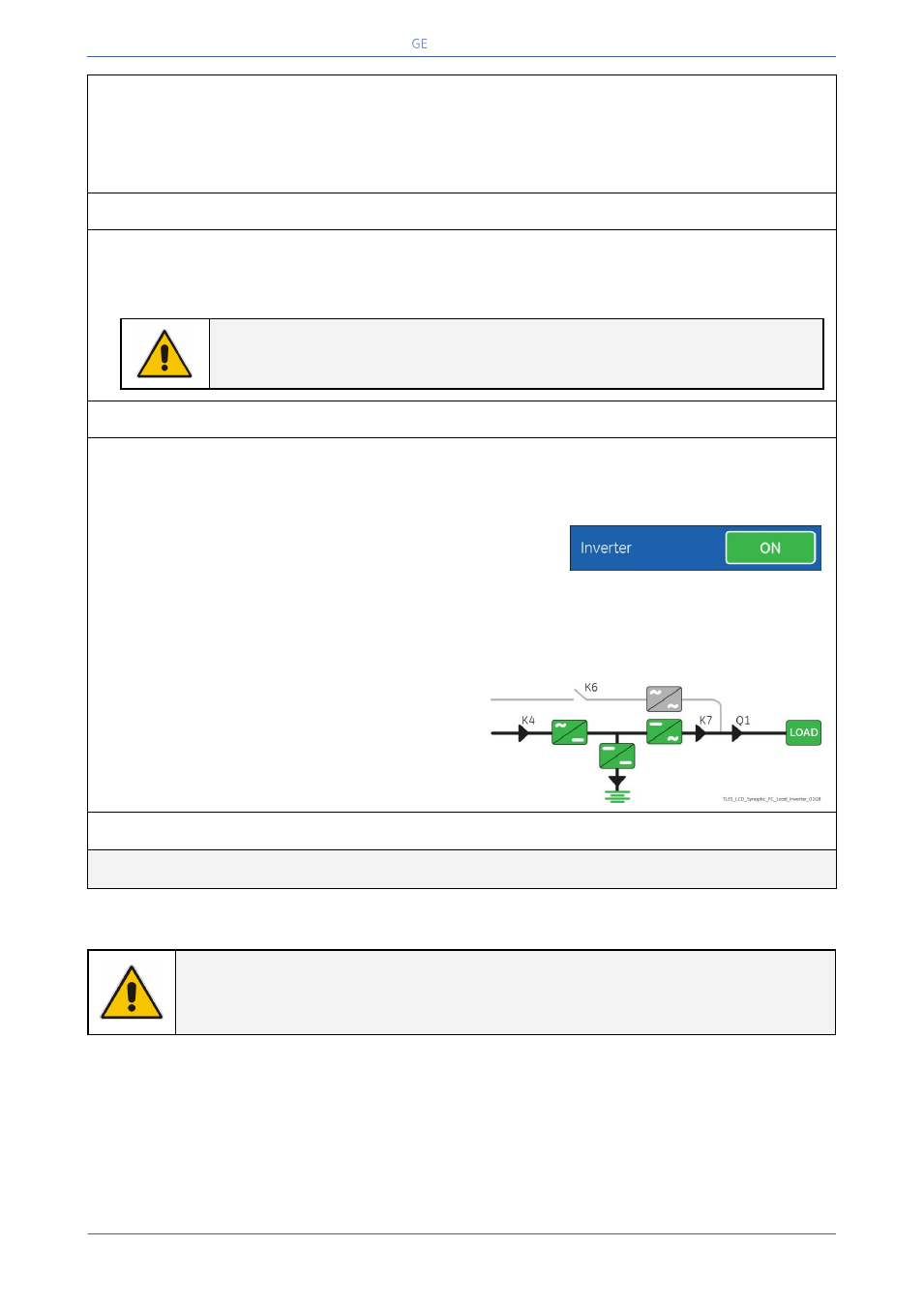
4. Insert the inverter performing the command “Inverter ON".
Before performing this procedure make sure that the LED 1 (Rectifier) and LED 3 (Booster/Battery
charger) are lit.
Perform the “Inverter ON” command from the screen:
Commands 1 / Inverter / ON.
Soft-start of Inverter indicated with blinking LED 2 (Inverter).
At the end of Soft-start the LED 2 (Inverter) remains lit.
Load is now supplied from Inverter.
LED ALARM turns Off and the LED LOAD PROTECTED must be lit.
The Synoptic Diagram must display the status “LOAD
SUPPLIED BY INVERTER”.
END OF PROCEDURE
NOTE !
The Battery must be charged for at least 10 hours, in order to ensure the full backup
runtime in case of a Utility Failure.