B&B Electronics MESR321_SL_ML - Manual User Manual
Page 13
Setup and Connections
Vlinx MESR321 Modbus Gateway
11
MESR321-xx_R001_2113m
www.bb-elec.com
www.bb-europe.com
3
3
.
.
S
S
e
e
t
t
u
u
p
p
a
a
n
n
d
d
C
C
o
o
n
n
n
n
e
e
c
c
t
t
i
i
o
o
n
n
s
s
Note: In this section devices to be connected to the Modbus gateway
’s serial
connection are simply referred to as the “Modbus network”.
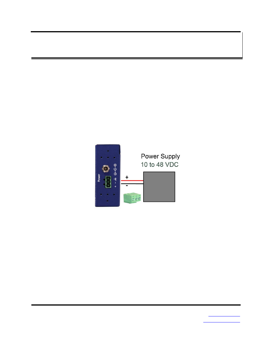
Connecting the Power Supply
Connect a DC power supply to the power terminals on the top of the Modbus
gateway. Polarity of the wires is indicated on the label on the side of the Modbus
gateway. Acceptable voltages are between 10 VDC and 48 VDC. The power
supply must be capable of supplying 4 watts.
Figure 8. MESR Power Connection
Connecting MESR321s to Modbus networks
MESR321s can be configured to connect to Modbus networks using RS-232,
RS-422, RS-485 2-wire and RS-485 4-wire.
RS-232 connections support eight signal lines plus Signal Ground. Signals are
single ended and referenced to Ground. Default communications parameters are
9600, 8, N, 1..
RS-422 4-wire connections support two signal pairs: RXA(-), RXB(+) and TXA(-),
TXB(+), plus GND. The data lines are differential pairs (A & B) in which the B line