Detailed description, Table 1. register configuration – Rainbow Electronics MAX3540 User Manual
Page 6
MAX3540
Complete Single-Conversion Television Tuner
6
_______________________________________________________________________________________
Detailed Description
Register Descriptions
The MAX3540 includes 11 programmable registers and
two read-only registers. The 11 programmable registers
include two N-divider registers, an R-divider register, a
VCO register, an RSSI/charge-pump/filter-select regis-
ter, a control register, a shutdown register, and tracking-
filter control registers. These 11 programmable regis-
ters are also readable. The read-only registers include
a status register and a ROM table data register.
Recommended default bit settings are provided for
user convenience only and are not guaranteed. The
user must write all registers after power-up and no ear-
lier than 100μs after power-up.
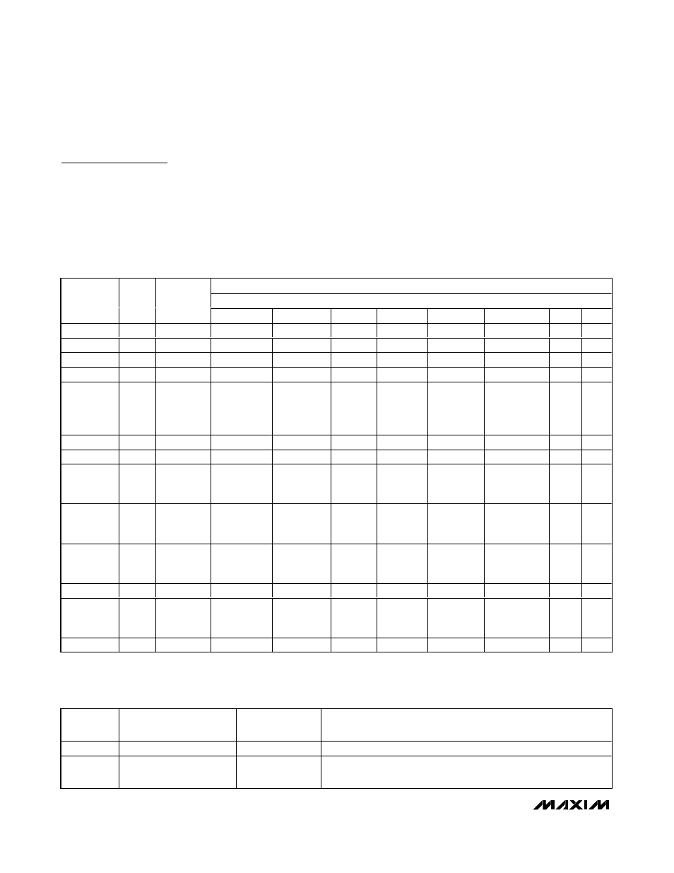
MSB LSB
DATA BYTE
REGISTER
NAME
R EA D /
W R I T E
REGISTER
ADDRESS
D7
D6
D5
D4
D3
D2
D1
D0
N-DIV High
Both
0x00
0
N14
N13
N12
N11
N10
N9
N8
N-DIV Low
Both
0x01
N7
N6
N5
N4
N3
N2
N1
N0
R-DIV
Both
0x02
0
R6
R5
R4
R3
R2
R1
R0
VCO
Both
0x03
VCO4
VCO3
VCO2
VCO1
VCO0
LD
VDIV1 V D IV 0
IFOVLD,
Charge
Pump, and
Filter Select
Both
0x04
0
IFOVLD2
IFOVLD1
IFOVLD0
CP1
CP0
TF1
TF0
Control
Both
0x05
0
0
0
0
SHDN_RF
SHDN_IFAGC INPT1 IN P T0
Shutdown
Both
0x06
S H D N _M IX 1 S
H D N _M IX 0 S
H D N _I F S H D N _P D S H D N _S Y N 0
0
0
Tracking
Filter Series
Cap
Both
0x07
TFS7
TFS6
TFS5
TFS4
TFS3
TFS2
TFS1
TFS0
Tracking
Filter
Parallel Cap
Both
0x08
FLD
0
TFP5
TFP4
TFP3
TFP2
TFP1
TFP0
Tracking
Filter ROM
Address
Both
0x09
0
0
0
0
TFA3
TFA2
TFA1
TFA0
Reserved
Both
0x0A
X
X
X
X
X
X
X
X
ROM Table
Data
Readback
Read
0x0B
TFR7
TFR6
TFR5
TFR4
TFR3
TFR2
TFR1
TFR0
Status
Read
0x0C
POR
LD2
LD1
LD0
X
X
X
X
Table 1. Register Configuration
BIT NAME
BIT LOCATION (0 = LSB)
RECOMMENDED
DEFAULT
FUNCTION
RESERVED
7
0
Must be set to 0.
N[14:8] 6–0
001
0010
Sets the most significant bits of the PLL integer divider (N). Default
integer divider value is N = 4688. N can range from 256 to 32,767.
Table 2. N-DIV High Register (Address: 0000
b
)