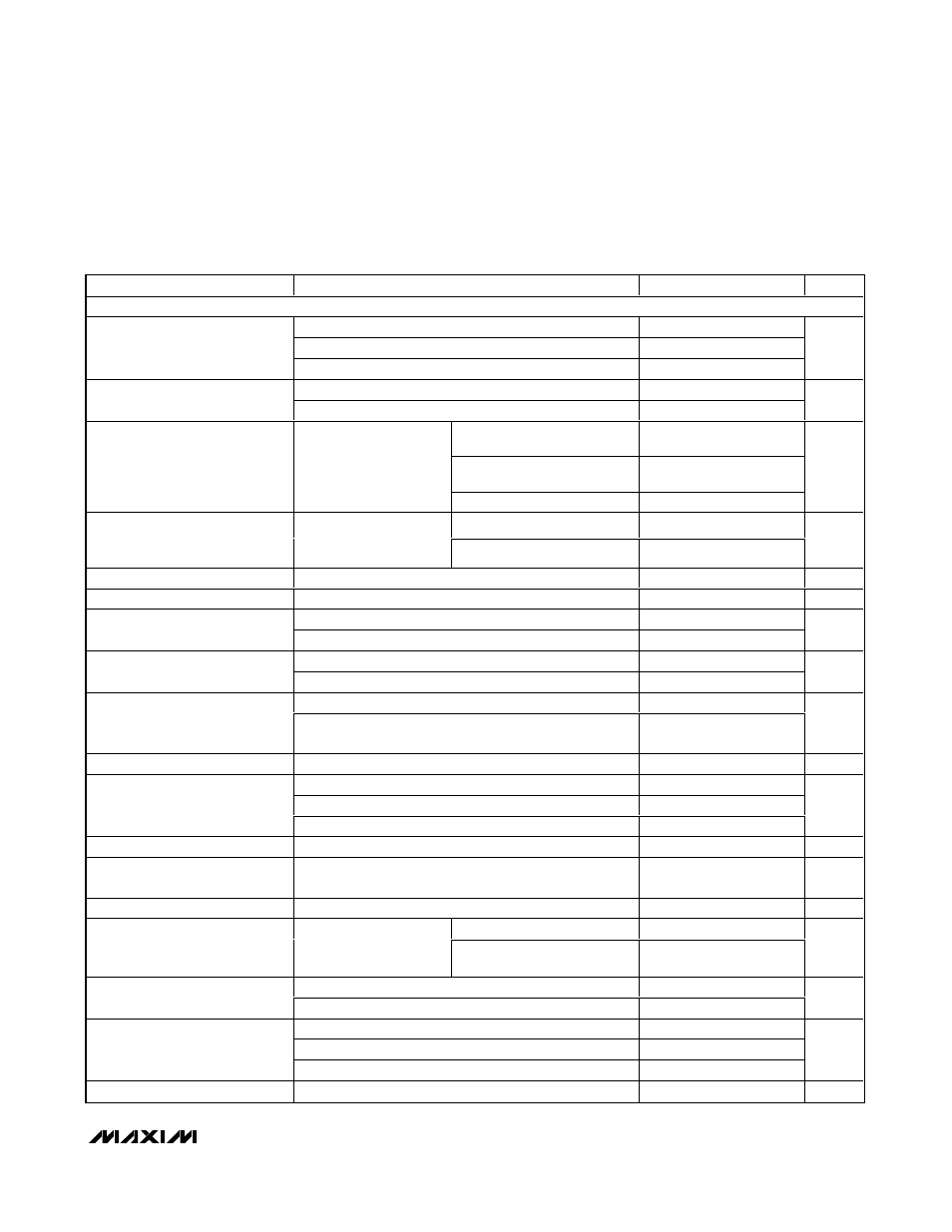
Ac electrical characteristics – Rainbow Electronics MAX3540 User Manual
Page 3
MAX3540
Complete Single-Conversion Television Tuner
_______________________________________________________________________________________
3
PARAMETER
CONDITIONS
MIN
TYP
MAX
UNITS
RF INPUT TO IFOUT1_ OUTPUT
VHF_IN, LPF enabled, INPT = 00
54
100
VHF_IN, LPF disabled, INPT = 01
100
300
Operating Frequency Range
(See Table 7)
UHF_IN, INPT = 10
300
860
MHz
Analog channel PIX carrier
45.75
Output Frequency
Digital channel center frequency
44
MHz
Maximum gain, V
RFAGC
= 3V,
54MHz to 860MHz
34
Maximum gain, V
RFAGC
= 3V,
broadcast channels
28.0
34
45.5
Voltage Gain
Source impedance =
75
Ω, load impedance =
200
Ω
M i ni m um g ai n, V
R FA GC
= 0.5V
-11
dB
VHF_IN
54
300
Operating Frequency Range
Gain specification met
across these frequency
bands
UHF_IN
300
860
MHz
Input Return Loss
Worst case, selected channel
8
dB
Noise Figure
Maximum gain, V
RFVGC
= 3V (Note 1)
4.4
dB
Maximum gain, V
RFVGC
= 3V
15
Input IP2
(In-Band and Out-of-Band Tones)
At 12.5dB of gain
29
dBm
Maximum gain, V
RFVGC
= 3V
-13
Input IP3
(In-Band and Out-of-Band Tones)
At 12.5dB of gain
5
11
dBm
Maximum gain, V
RFVGC
= 3V
-24.5
Input P
1dB
At 12.5dB of gain, CW tone at f
C
- 36MHz, tested at Ch
69 in UHF band
-3
dBm
Beats Within Output
0dBmV PIX carrier level (Note 1)
-60
dBc
VHF_IN from 150MHz to 960MHz
-60
VHF_IN from 960MHz to 1400MHz
-40
Beats, Converted to Output
UHF_IN from 600MHz to 1400MHz
-40
dBc
Gain Flatness
54MHz to 60MHz
1.5
dB
P-P
Isolation
5MHz to 50MHz, RF input to IF output, relative to desired
channel
60
dBc
Port-to-Port Isolation
Isolation between RF input ports at 215MHz
30
dB
54MHz to 860MHz
70
Image Rejection
Measured at 91.5MHz
above desired channel’s
center frequency
Broadcast channels,
T
A
= +25
°C
66
dBc
5MHz to 65MHz
-40
Spurious Leakage at RF Input
65MHz to 878MHz
-40
dBmV
10kHz offset
-85
100kHz offset, 1.5kHz loop bandwidth
-105
Phase Noise (Single-Sideband)
1MHz offset, 1.5kHz loop bandwidth
-125
dBc/Hz
Output Return Loss
Balanced 50
Ω load
9
dB
AC ELECTRICAL CHARACTERISTICS
(MAX3540 Evaluation Kit, V
CC
= +3.1V to +3.5V, 75
Ω system impedance, default register settings, V
RFAGC
= V
IFAGC
= +3V (minimum
attenuation), T
A
= 0°C to +85°C, unless otherwise noted. Typical values are at V
CC
= +3.3V, T
A
= +25°C, unless otherwise noted.)