Rainbow Electronics DS2132A_Q User Manual
Page 8
DS2132A/Q
041295 8/17
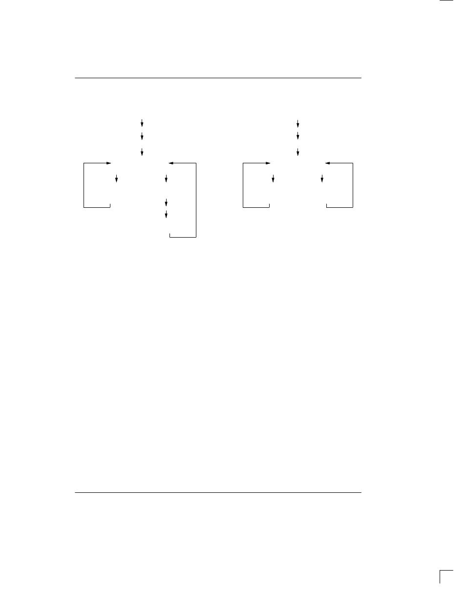
RECORD & PLAYBACK FLOWCHARTS Figure 7
Write Command Byte
to set the gain
Read Status Byte
Write Command Byte
to begin recording
Read Status Byte;
does MSB = 1?
Record Flowchart
Playback Flowchart
Write Command Byte
to set the gain
Read Status Byte
Write Command Byte
to begin playback
Read Status Byte;
does MSB = 1?
no
yes
no
yes
Write Command
Byte
Read Data Byte
Write Command
Byte
Write Command
Byte
Write Data Byte
Write Command
Byte
LOOPBACK MODE
The DS2132A contains a Loopback Mode that is useful
in debugging the CODEC to DS2132A interface and in
adjusting the analog circuits to the proper gain/attenua-
tion levels. In the Loopback Mode, the DS2132A routes
the incoming digitized audio signal received at the
PCMIN pin, back to the PCMOUT pin after making gain
adjustments. See Figure 2. Notice that the route in-
cludes the record and playback gain circuits. The Loop-
back mode can be enabled at any time. When the Loop-
back is enabled, the generated tones or expanded
speech are ignored. See Figure 2. The DS2132A will
enter the Loopback mode if a Command Byte of [08] is
sent to it by the microcontroller. The Loopback mode
will be exited upon receiving the Exit Loopback Mode
command.
FAX CALLING TONE DETECT
According to CCITT Recommendation T.30, originating
automatic FAX machines should transmit an 1100 Hz
tone for 0.5 seconds every 3.5 seconds (on for 0.5’s; off
for 3.0’s). This tone is meant as an indication to the
called station that a non-voice instrument is making the
call. The Status Byte in the DS2132A reports if a
1100 Hz tone is being received. This detection can be
used to determine if a FAX machine has called the an-
swering machine. The answering machine will then
know not to record the incoming call and to route the call
to a FAX machine.