Rainbow Electronics DS2132A_Q User Manual
Page 3
DS2132A/Q
041295 3/17
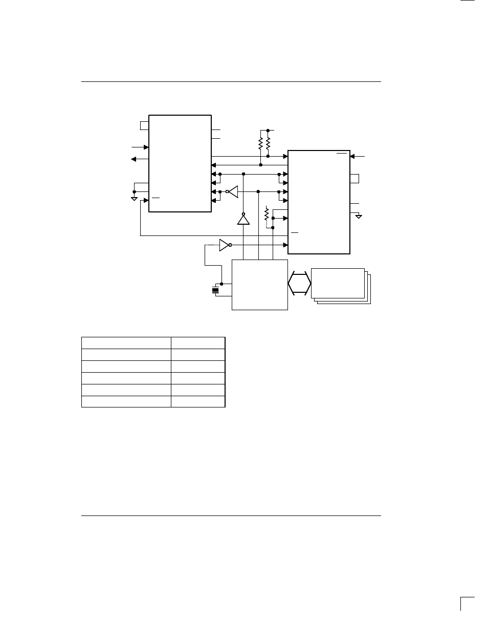
TYPICAL DIGITAL ANSWERING SYSTEM Figure 1
-5V
Microcontroller
GA1
GA2
AIN
AOUT
DGND
AGND
PCMOUT
PCMIN
TXCLK
RXCLK
TXSYNC
RXSYNC
VSS
VDD
+5V
PD
PCMIN
PCMOUT
CLK
FS
CDOUT
CDIN
MCLK
RST
POR
TRI_OUT
TRI_IN
CLK
FS
VCC
GND
+5V
+5V
+5V
DRAM Array
8051-Type
P1.1
TXD
P1.0
RXD
Note:
HD44238P is a Hitachi CODEC
CODEC/FILTER
DS2132A
To 2- to 4–wire
converter and phone line
interface
PD
12 MHz to 16 MHz
RECOMMENDED DS2132A CODECS Table 2
Vendor
Model(s)
Texas Instruments
TCM29CXX
National Semiconductor
TP3054X
Motorola
MC1455XX
SGS–Thomson
ETC505X
Hitachi
HD44238C
As shown in Figure 1, the microcontroller creates the
clock (CLK) and frame sync (FS) that is sent to both the
CODEC and the DS2132A. In this manner, the
DS2132A shares the signals necessary to drive the CO-
DEC. To “record” an audio signal, the following occurs.
The analog signal applied at the AIN pin of the CODEC
is converted to eight bit values and output at PCMOUT
every 125
µ
s. The DS2132A takes these eight bit sam-
ples in at the PCMIN pin and effectively compresses
them to either 9.8Kbps or 4.9Kbps. See Figure 2. The
compressed data is then passed to the microcontroller
via the CDOUT pin (CD stands for Compressed Data).
The microcontroller then stores the compressed
speech in the DRAM array. The inverse of this process
is required to “playback” the message at the AOUT pin
of the CODEC.