Rainbow Electronics DS2132A_Q User Manual
Page 7
DS2132A/Q
041295 7/17
There are three types of bytes that can be transferred on
the CD Port; Command Bytes, Status Bytes, and Com-
pressed Speech Data Bytes (or simply Data Bytes).
The Command Bytes are always transferred from the
microcontroller to the DS2132A to instruct the proces-
sor to perform a particular task like transmit a tone. All of
the possible commands that can be sent to the
DS2132A are listed in Table 3. Status Bytes are always
transferred from the DS2132A to the microcontroller.
They inform the microcontroller if a DTMF digit is being
received, or what the current energy level is. See Figure
6. Finally, there are Data Bytes which are transferred
from the DS2132A to the microcontroller during a “re-
cording” and from the microcontroller to the DS2132A
during a “playback”. See Figure 5. When recording, the
microcontroller must read the MSB of the Status Byte to
discriminate between Data Bytes and Status Bytes.
When playing back, the microcontroller must read the
MSB of the Status Byte to know when to send a Com-
mand Byte and when to send a Data Byte.
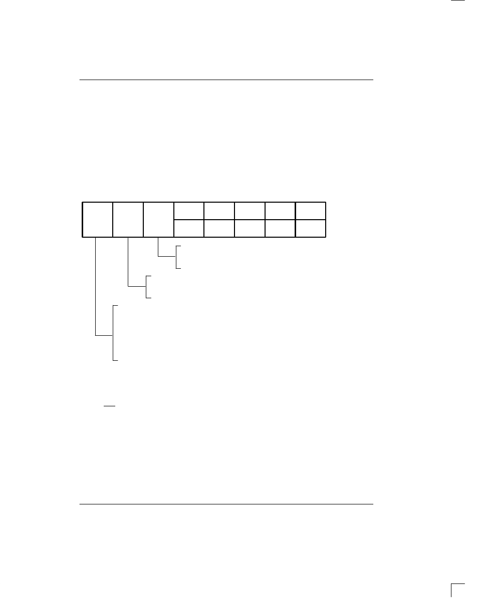
STATUS BYTE FORMAT Figure 6
CDFA
DV
FCNG
L4
0
L3
D3
L2
D2
L1
D1
L0
D0
(MSB)
(LSB)
DV = 0
(see Table 4)
DV = 1
(see Table 5)
FAX Calling Tone Detect
0 = 1100 Hz tone not present
1 = 1100 Hz tone present
DTMF Digit Valid
0 = no DTMF digit detected; received energy level reported at L0 to L4 bits
1 = DTMF digit detected; the digit is reported at D0 to D3 bits
Compressed Data Frame Alert
Record Mode:
0 = next CD Port output is a Status Byte
1 = next CD Port output is a Data Byte
Playback Mode:
0 = next CD Port input is a Command Byte
1 = next CD Port input is a Data Byte
Tone Generation or Idle: Will always be set to 0.
SYNCHRONIZING THE CD PORT
On power-up, the first task of the microcontroller is to
“synchronize” the CD Port. It can accomplish this by lis-
tening to what the DS2132A is sending it. On power-up
(after the RST pin is returned high), the DS2132A will be
in the Idle mode awaiting a command from the micro-
controller. Hence it will be alternately sending a Status
Byte to the microcontroller and taking in a Command
Byte. In Figure 1, there is a pull-up resistor on the CD
Port to insure that on power-up, the microcontroller will
send the “no update” command to the DS2132A, which
is [FF]. When the microcontroller reads a value other
than [FF], then it knows that the byte it just read is a Sta-
tus Byte and hence it will then know that the next byte
will be a Command Byte and it will be synchronized.
RECORD & PLAYBACK MODES
Figure 7 shows two brief flowcharts on what actions the
microcontroller would follow to instruct the DS2132A to
compress (Record Mode) or expand speech (Playback
Mode) data. Before a recording or a playback is to be-
gin, it is recommended that the microcontroller first set
the gain to a nominal position. Then, if needed, the gain
can be adjusted as the recording or playback is occur-
ring. For example, as the recording process begins, the
microcontroller can monitor the incoming speech ener-
gy levels via the Status Byte. If the incoming speech lev-
el is too low or too high, the gain can be adjusted accord-
ingly. The microcontroller can exit the Recording or
Playback Modes by sending the Idle command.