Rainbow Electronics DS2132A_Q User Manual
Page 11
DS2132A/Q
041295 11/17
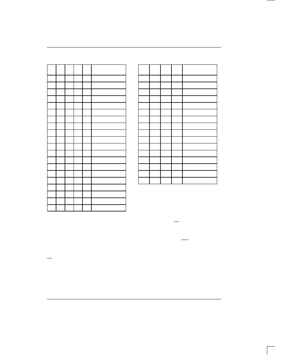
DEFINITION OF THE L0 TO L4 LEVEL BITS
Table 4
L4
L3
L2
L1
L0
ENERGY LEVEL
RECEIVED
0
0
0
0
0
<-48dBm0
0
0
0
1
0
-45dBm0
0
0
1
0
0
-42dBm0
0
0
1
0
1
-39dBm0
0
0
1
1
0
-36dBm0
0
0
1
1
1
-33dBm0
0
1
0
0
0
-30dBm0
0
1
0
0
1
-27dBm0
0
1
0
1
0
-24dBm0
0
1
0
1
1
-21dBm0
0
1
1
0
0
-18dBm0
0
1
1
0
1
-15dBm0
0
1
1
1
0
-12dBm0
0
1
1
1
1
-9dBm0
1
0
0
0
0
-6dBm0
1
0
0
0
1
-3dBm0
1
0
0
1
0
0dBm0
1
0
0
1
1
+3dBm0
1
0
1
0
0
+6dBm0
1
0
1
0
1
+9dBm0
DEFINITION OF THE D0 TO D3 DTMF BITS
Table 5
D3
D2
D1
D0
DTMF DIGIT
DETECTED
0
0
0
0
DTMF Digit “0”
0
0
0
1
DTMF Digit “1”
0
0
1
0
DTMF Digit “2”
0
0
1
1
DTMF Digit “3”
0
1
0
0
DTMF Digit “4”
0
1
0
1
DTMF Digit “5”
0
1
1
0
DTMF Digit “6”
0
1
1
1
DTMF Digit “7”
1
0
0
0
DTMF Digit “8”
1
0
0
1
DTMF Digit “9”
1
0
1
0
DTMF Digit “A”
1
0
1
1
DTMF Digit “B”
1
1
0
0
DTMF Digit “C”
1
1
0
1
DTMF Digit “D”
1
1
1
0
DTMF Digit “*”
1
1
1
1
DTMF Digit “#”
POWER-DOWN MODE
The DS2132A can be placed into a low-power standby
condition by sending the enter power-down command
[04] to the DS2132A. The DS2132A will power down
within 500
µ
s after receiving the power-down command.
The MCLK signal should still be applied to the DS2132A
in the power-down mode. The CLK and FS signals may
be either stopped or continued. In the power-down
mode, the DS2132A will consume about 1 mA and the
PD pin (Pin 1) will be forced low and the PD pin (Pin 5)
will be forced high. The PD and PD pins can be used to
power-down the CODEC. See Figure 2. To exit the pow-
er-down mode, the exit power-down command [05]
should be sent to the DS2132A. There is no need to is-
sue a hardware reset via the RST pin; the device will re-
set itself. The DS2132A will power-up in the Idle mode.
The microcontroller should wait 1 ms after issuing the
exit power-down command before reinitializing the
device.