Ds1841 temperature-controlled, nv, i, C, logarithmic resistor, Table 3. lut registers and temperature ranges – Rainbow Electronics DS1841 User Manual
Page 8
DS1841
Temperature-Controlled, NV, I
2
C,
Logarithmic Resistor
8
_______________________________________________________________________________________
Temperature Conversion and Supply
Voltage Monitoring
Temperature Conversion
The DS1841 features an internal 8-bit temperature sen-
sor that can drive the LUT and provide a measurement
of the ambient temperature over I
2
C by reading the
value stored in address 0Ch. The sensor is functional
over the entire operating temperature range and is
stored in signed two’s complement format with a resolu-
tion of 1°C/bit. See Table 2, Register 0Ch description for
the temperature sensor’s bit weights. To calculate the
temperature, treat the two’s complement binary value as
an unsigned binary number, then convert it to decimal.
If the result is greater than or equal to 128, subtract 256
from the result.
LUT
The DS1841 monitors the internal temperature by
repeatedly polling the sensor’s result with update rate
t
FRAME
. During each cycle, the DS1841 reads the inter-
nal temperature, and, based on that temperature,
points to the corresponding LUT address. Every two
degrees of temperature will convert into one tempera-
ture address slot. See Table 3 for a list of temperatures
and their corresponding LUT addresses.
The LUT features one-degree hysteresis to prevent
chattering if the measured temperature falls on the
boundary between two windows (see Figure 1).
Table 3. LUT Registers and Temperature Ranges
TEMPERATURE (°C)
TEMPERATURE VALUE FOR GIVEN
TEMPERATURE (HEX)
CORRESPONDING LUT ADDRESS
(HEX)
-40 or less
D8
80
-39 to -38
D9 to DA
81
-37 to -36
DB to DC
82
-35 to -34
DD to DE
83
— — —
+95 to +96
5F to 60
C4
+97 to +98
61 to 62
C5
+99 to +100
63 to 64
C6
+101 or more
65
C7
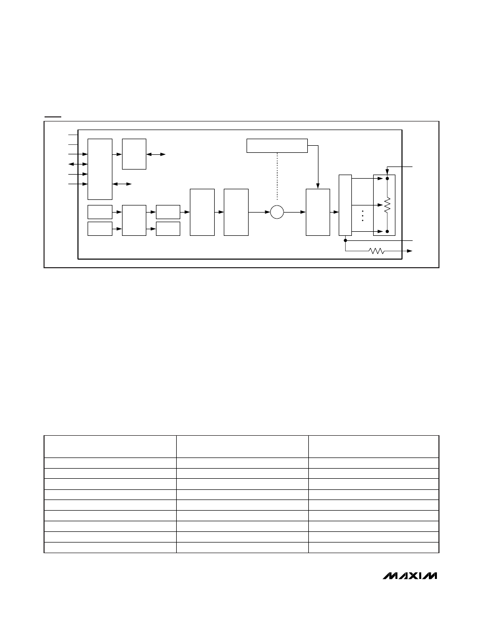
LUT Mode and LUT Adder Mode Block Diagram (Update Mode Bit = 1)
1 OF 128 MULTIPLEXERS
IVR
ON POWER-UP
ONLY WHEN IN
LUT ADDER MODE
INITIAL VALUE REGISTER (IVR)
00h*
CONTROL
LOGIC/
REGISTERS
LUT
ADDRESS
REGISTER
(LUTAR)
08h
72-BYTE
LOOKUP
TABLE
(LUT)
80h–C7h
WIPER
REGISTER
(WR)
09h*
ADC
I
2
C
INTERFACE
TEMP
SENSOR
V
CC
VOLTAGE
TEMP
0Ch
V
CC
(V)
0Eh
V
CC
GND
SCL
SDA
A0
A1
POS 7Fh
POS 00h
R
S
RGND
RW
RH
CONTROL
DATA
*NOTE THAT WHEN IN LUT OR LUT ADDER MODE, WR IS ACCESSED THROUGH 09h WHILE IVR REMAINS AT 00h.
∑
LUTVAL
LUTVAL
OR
LUTVAL+IVR