Ds1841 temperature-controlled, nv, i, C, logarithmic resistor – Rainbow Electronics DS1841 User Manual
Page 4
DS1841
Temperature-Controlled, NV, I
2
C,
Logarithmic Resistor
4
_______________________________________________________________________________________
Note 1: All voltages are referenced to ground. Currents entering the IC are specified positive and currents exiting the IC are
negative.
Note 2: I
CC
is specified with the following conditions: SCL and SDA = V
CC
, RW and RH floating with Update Mode bit = 1.
Note 3: This is the minimum V
CC
voltage that causes NV memory to be recalled.
Note 4: This is the time from V
CC
> V
POR
until initial memory recall is complete.
Note 5: Guaranteed by design.
Note 6: I
2
C interface timing shown is for Fast-Mode (400kHz) operation. This device is also backward-compatible with I
2
C-
Standard Mode timing.
Note 7: C
B
—total capacitance of one bus line in picofarads.
Note 8: EEPROM write time begins after a STOP condition occurs.
Note 9: Guaranteed by characterization.
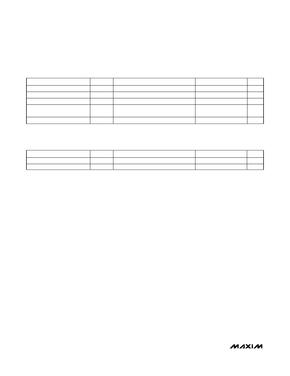
I
2
C AC ELECTRICAL CHARACTERISTICS (See Figure 3) (continued)
(V
CC
= +2.7V to +5.5V, T
A
= -40°C to +100°C, timing referenced to V
IL(MAX)
and V
IH(MIN)
.)
PARAMETER
SYMBOL
CONDITIONS
MIN
TYP
MAX
UNITS
EEPROM Write Time
t
W
(Note 8)
10
20
ms
A0, A1 Setup Time
t
SU:A
Before
START
0.6
μs
A0, A1 Hold Time
t
HD:A
After
STOP
0.6
μs
Input Capacitance on
A0, A1, SDA, or SCL
C
I
5
10
pF
Startup Time
t
ST
2
ms
NONVOLATILE MEMORY CHARACTERISTICS
(V
CC
= +2.7V to +5.5V)
PARAMETER
SYMBOL
CONDITIONS
MIN
TYP
MAX
UNITS
EEPROM Write Cycles
T
A
= +85°C
50,000
Writes
EEPROM Write Cycles
T
A
= +25°C (Note 9)
200,000
Writes