Ds1841 temperature-controlled, nv, i, C, logarithmic resistor, Pin description – Rainbow Electronics DS1841 User Manual
Page 6: Detailed description, Table 1. operating modes
DS1841
Temperature-Controlled, NV, I
2
C,
Logarithmic Resistor
6
_______________________________________________________________________________________
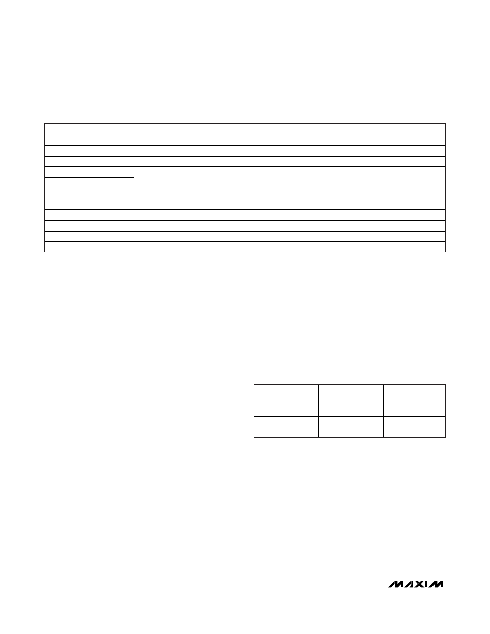
Pin Description
PIN
NAME
FUNCTION
1 SDA
I
2
C Serial Data. Input/output for I
2
C data.
2 GND
Ground
3 V
CC
Power Supply
4 A1
5 A0
Address Select Inputs. Determines I
2
C slave address. Device address is 01010A
1
A
0
X (see the
Slave Address Byte and Address Pins sections for more details).
6
RGND
Low Terminal of Resistor. Must be connected to GND.
7 RW
Wiper
Terminal
8
RH
Terminal with Fixed Resistor Added in Series with Digital Resistor
9 N.C.
No
Connection
10 SCL
I
2
C Serial Clock. Input for I
2
C clock.
—
EP
Exposed Paddle. Must be connected to ground.
Detailed Description
The DS1841 operates in one of two modes: LUT Mode
and LUT Adder Mode. In LUT Mode and LUT Adder
Mode, the resistor’s wiper position is controlled as a
function of the temperature measured by the DS1841’s
internal temperature sensor. The difference between
the two LUT modes is the way the resistor’s wiper posi-
tion is calculated. Detailed descriptions of these two
modes, as well as additional features of the DS1841,
are discussed in subsequent sections.
Digital Resistor Description
The DS1841’s resistor consists of 128 resistive steps
between RW and RGND with a series resistor, R
S
,
between RH and RW. The wiper position and the output
seen on RW are decoded based on the value in the
wiper register (WR). The step size of each position is
optimized to produce a linear response when used in
the feedback network of a DC-DC converter.
Mode Selection
The DS1841 mode of operation is determined by the
Update Mode bit (Control Register 1, address 03h, bit 0)
and the Adder Mode bit (Control Register 1, address
03h, bit 1). Table 1 illustrates how the two control bits
are used to select the operating mode. When shipped
from the factory, the DS1841 is programmed with the
Update Mode and Adder Mode bits set to 1, hence con-
figuring the DS1841 in LUT Adder Mode. See Appendix
A for a detailed table of the control logic bit functions.
Table 1. Operating Modes
UPDATE MODE
BIT
ADDER MODE BIT
MODE
1 0
LUT
Mode
1 1
LUT Adder Mode
(Default)