Baron Air & Fuel_BIG AIR KIT STEALTH Road_Stratoliner & Raider User Manual
Page 5
Page: 5
BA-2021-00
STEALTH BIG AIR KIT - Yamaha Roadliner/Stratoliner and
Raider
YOU MAY PROCEED AFTER THE COILS AND ELECTRICAL CONNECTIONS ARE CLEARLY MARKED.
2. Using a 5mm allen wrench remove the upper and lower bolts securing each coil to their mount brackets. Disconnect the black & white
electrical leads from the bottom of each coil. Remove the spark plug cap from the plugs and set each coil aside. Some of the plug wires will be zip
tied to the upper frame rail. Cut these zip ties to release the wires, then use a supplied zip tie to re-secure the rubber dampers and other wires to
the frame.
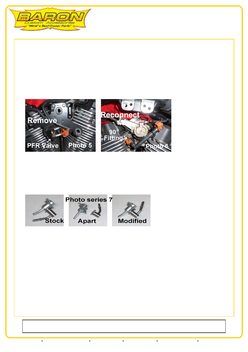
PRESSURIZED FUEL RETURN VALVE:
3. Remove the coil mounting brackets and set them aside. Remove the bracket attaching the pressurized fuel return valve and let it hang. You
will not reuse the stock coil mounts for re-mounting the coils but may use them for remounting the stock side covers at the end of the
installation. See photo 5:
4. Remove the left motor mount from the left side of the engine by removing the (2) 10mm dome head allen bolts at the top of the motor mount
using an 8mm allen Wrench, then remove the (2)14mm hex nuts at the bottom of the mount secured to the top of each cylinder. See photo 6
above:
5. You can now easily access and release the pinch clamp on the rubber hose connected to the end of the pressurized fuel return valve which
connects to the hard (metal) fuel line. Remove the hard line from the short rubber hose, then release the pinch clamp on the long rubber hose
connected to the other end of the hard fuel line and remove the hard line from the bike. You will not reuse this hard line. See photo 6 above:
CAUTION: This is a fuel return line and is connected to the secondary fuel tank. A small amount of fuel usually escapes from this line during
removal. Once removed it is important plug or keep the open end raised so no additional fuel escapes.
6. The pressurized fuel return valve must be pulled apart and the nipple rotated 180 degrees and then pushed back together. See photo series 7:
NOTE: The pressurized fuel return valve lines on the RAIDER have a black connection at the short 90 degree end and an orange connection at
the straight end. The LINERS have orange connections at both ends. It is important/mandatory the short 90 degree end be connected to the
base of the throttle body. Photo
7. If the 90 degree end is not connected to the base of the throttle body you must remove and rotate the line and make the connection properly at
this time. See photo 6 above:
8. Pressurized fuel return valve FITTING DISCONNECTION: Slide the black or orange plastic safety lock back from the fitting, this exposes
two Gray buttons on either side of the connection. You must depress both buttons while simultaneously pulling the connections away from the
nipple.
9. Attach the pressurized fuel return valve to the new small black bracket (supplied) using (2) m5 x 16 cap head screws (supplied) See photo 8:
NOTE: The mount tab from the pressurized fuel return valve sits on the inside of the new mount. The cap head screws go through the
pressurized fuel return valve mount tab and thread into the new black bracket and should be tightened firmly. See photo 8:
Our install guides provide a basic outline on the proper installation of our products. Further tuning and/or
fitment may be required. Barons bears no responsibility on installation costs associated with this product.
© 2013 Barons Custom Accessories
5221 Oceanus Drive
Huntington Beach, CA 92649
(925)583-2499 - Ph.
(714)901-0520 - Fax
www.baronscustom.com