Baron Air & Fuel_BIG AIR KIT STEALTH Road_Stratoliner & Raider User Manual
Page 4
Page: 4
BA-2021-00
STEALTH BIG AIR KIT - Yamaha Roadliner/Stratoliner and
Raider
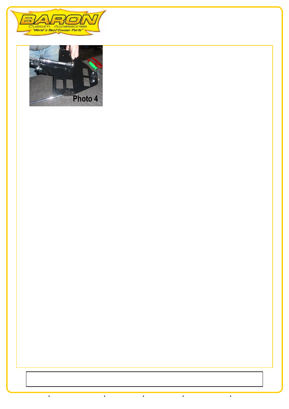
8. Place the coil mount plate over the top of the filters and align the front mount hole with the center frame mount hole where the frame rails
come together. Insert the stock allen bolt and start the threads but do not tighten at this time.
9. Using an 8mm allen wrench remove the upper front motor mount bolt from the bracket. Replace it with the supplied M10-1.25 x 35mm cap
head allen bolt and 10mm flat washer and thread this bolt into the motor mount hole until the head of the stud is even with the inside of the
frame. Looking towards the front of the bike from under the coil mount plate locate the bolt head and then align the 10mm hole in the 90 degree
mounting flange with the head of the bolt, and thread the bolt in and tighten fully. This will secure the left side of the coil mount plate.
NOTE: There are two holes in the right flange of the coil mount plate. The Raiders align with the rear hole and Liners align with the front
hole. The correct hole will naturally align with the front motor mount bolt.
10. The small 90 degree flange located on the right side of the coil mount plate opposite the large left flange. Be sure the small flange inserts into
the space between the outside of the frame rail and inside of the right motor mount bracket.
11. Notice the small rectangular slot in the top of the coil mount plate located 1.5" to the left of the right side of the mount flange. Take one of
the supplied zip ties and insert it downward through the right motor mount and reach under the coil mount plate with your fingers and direct
the zip tie around the frame rail and back up through the small hole then zip the tie through the head and tighten. Be sure the zip tie head is
sitting over the slot in the frame rail on the outside of the coil mount plate once tightened.
12. Tighten the allen bolt at the front coil mount plate mount.
TUNING: In order to maximize performance we recommend the installation of a Power Commander® by an authorized Power Commander®
Tuning Center.
NOTE: If you are installing a Power Commander® to maximize performance it will be much easier to install it at this time rather than having
to remove the fuel tank again. The electrical connections are easily accessible at this time. With aftermarket or stock exhaust you may safely
operate your bike without a Power Commander® and maintain a safe air/fuel mixture. However, as stated above, maximum performance will
not be attained unless you are using a Power Commander® or equal modifier.
INSTALLATION IS COMPLETE: You may now re-install the fuel tank, reconnect the fuel lines, install the left side cover and your seat.
NOT RECOMMENDED: We do not recommend EFI modifiers like the Cobra, Techlusions or similar as they have not proven beneficial in these
applications.
STAGE II
1. Remove the allen bolts from the left and right side covers using a 5mm allen wrench. Then pull the cover firmly straight away from the sides
to release the inner mount nipple from the rubber grommet. Set the covers aside.
RAIDER: On the left side of the engine detach the rubber vacuum lines from frame and mounts that lead away from the two small black
canisters. Using a 3mm allen wrench remove the small bolt on the right of the coil mount securing the two small black canisters. Set this aside.
LINERS: On the left side of the frame below the neck detach the rubber vacuum lines from frame and mounts that lead away from the two
small black canisters. Using a 3mm allen wrench remove the small bolt on the right of the coil mount securing the two small black canisters. Set
this aside.
COIL REMOVAL:
RAIDER: Four coils are visible. Mark all coils and their respective electrical leads connecting to the bottom of each coil sides so you can identify
them for re-installation. Trace the wires from the spark plugs to each coil body and mark as follow: RF = RIGHT FRONT, RR = RIGHT
REAR, LF = LEFT FRONT, LR = LEFT REAR
LINER MODELS: Two coils are visible and two are hidden inside the front frame neck, you will only be working with the two coils you can see
on the right hand side of the engine. These are located on the right side of the engine and both go to the rear cylinders. Mark coils and their
respective electrical leads connecting to the bottom of each coil sides so you can identify them for re-installation. Trace the wires from the spark
plugs to each coil body and mark as follow: RR= RIGHT REAR & LR = LEFT REAR
Our install guides provide a basic outline on the proper installation of our products. Further tuning and/or
fitment may be required. Barons bears no responsibility on installation costs associated with this product.
© 2013 Barons Custom Accessories
5221 Oceanus Drive
Huntington Beach, CA 92649
(925)583-2499 - Ph.
(714)901-0520 - Fax
www.baronscustom.com