Baron Air & Fuel_BIG AIR KIT STEALTH Road_Stratoliner & Raider User Manual
Page 3
Page: 3
BA-2021-00
STEALTH BIG AIR KIT - Yamaha Roadliner/Stratoliner and
Raider
INSTALLING NEW FILTER ASSEMBLY:
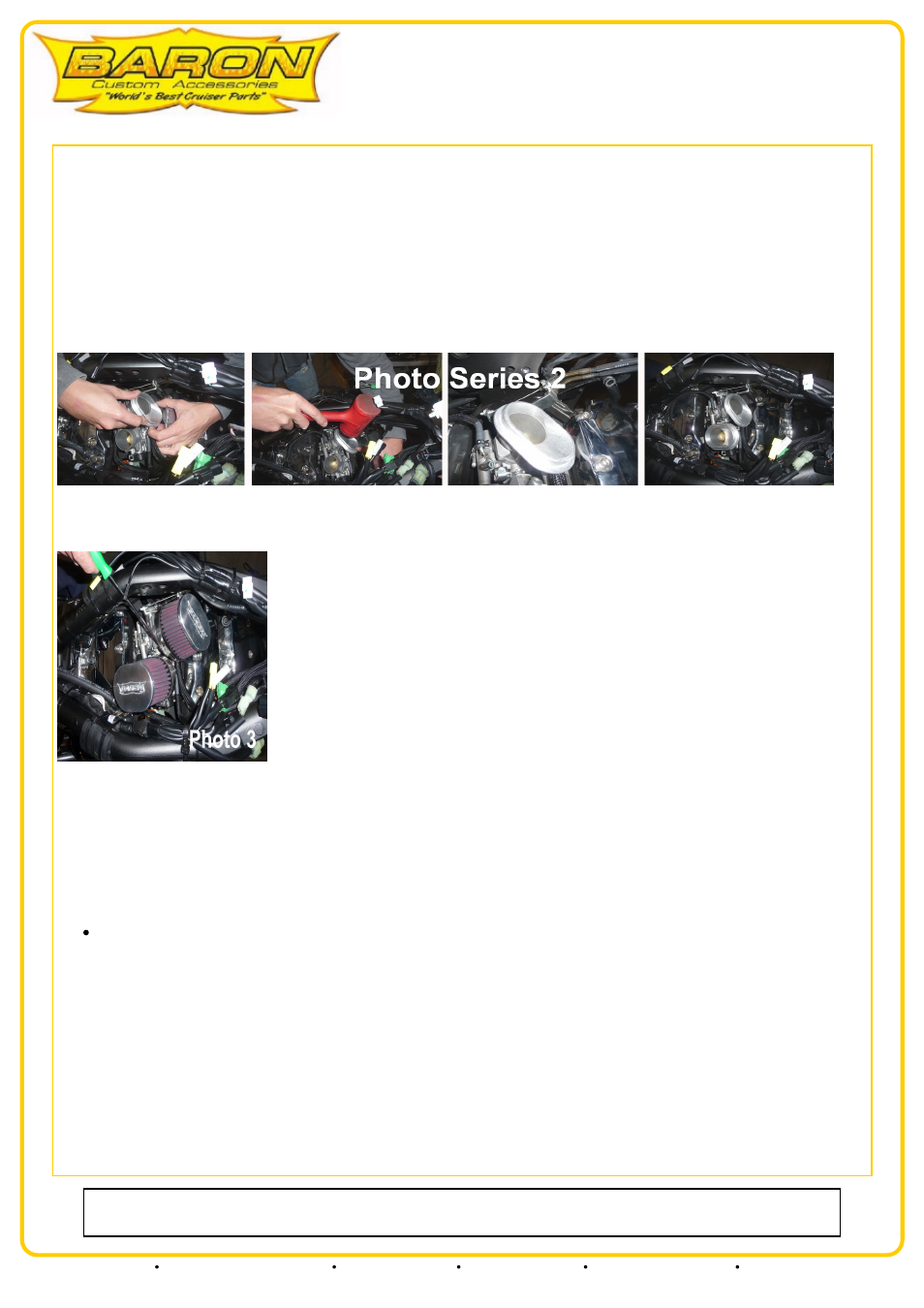
The left velocity filter base will sit with the oblong portion pointed to the 2:00 position being sure it is not touching the cylinder head and the right
velocity filter base will sit at the 12:00 position.
NOTE: These velocity filter bases are a tolerance fit so they require firm constant pressure to install. See photo series 2:
1. Take the velocity filter base and install the o-rings into the slots in the base of each unit if they are not already installed.
2. Place a velocity filter base down over the top of the throttle body until the o-ring contacts the top of the throttle body, now press down firmly on the
velocity base to get the o-ring to slide past the top and down the body until the top of the throttle body is evenly aligned with the lip on the inside of the
base above the o-ring. When the base is on correctly you will see an even seem around the entire circumference. If the seam is not even you must adjust
with pressure until it is. It may be necessary to use a soft blow mallet to attain a proper fit. Install on each throttle body.
DO NOT moisten or lubricate these o-rings or the metal around them. See photo series 2:
3. Loosen the screw clamp on the new high flow filter/s. Look inside each filter and you will see the point of the power cone, be sure the filter is installed
on the velocity filter base with the point directly over the center of the throttle body. Be sure the clamp screws are placed on the side and direction of
the filters that allows you to get your tool on them. Tighten the clamp being sure to not over-tighten it or the filter will be driven off the velocity filter
base. Repeat on both sides. See photo 3:
4. Check the left filter to be sure it is not touching the head. Rotate the base for clearance if necessary. Check to be sure the throttle linkage bracket is
not touching the filter. If it is touching, pull/tweak the bracket outward slightly as needed.
5. Install the UP-123 uni-filter on the hose you disconnected from the front of the air box earlier. Use the supplied screw clamp to secure it to the hose.
Take a zip tie and attach the filter to the vacuum lines or wiring harness to hold it high enough so it cannot be seen from the side of the bike.
6. Install the rubber hose supplied in the kit on to the crankcase vent spout on top of the rear cylinder, reuse the clamp that previously secured the
original crankcase vent hose in position. Install the UP-122 uni-filter on to the end of this hose and secure with supplied clamp.
TIME FOR A DECISION:
At this point, if you wish to leave your coils and stock engine side covers in place, move on to steps 7 thru 12. Re-install the fuel tank, seat and
side cover. You are now ready to visit the local tuning shop to maximize performance with the installation of a Power Commander®. However if
you wish to clean up the sides of your engine by removing these covers and all the related clutter contained under and around these covers then
proceed to STAGE II section bypassing steps 7 thru 12 at this time.
AIR SENSORS:
7. Take the black coil mount plate and attach the air sensors you removed from the stock air box earlier and attach them as follows. Using the
supplied m6-1.0 x 16mm cap head allen bolts and m6 flange nut attach one sensor to the very rear of the coil mount plate to the two holes located
in the bent tail section. The air nozzle/spout will point towards the engine. Attach the front air sensor to the foremost two parallel 6mm holes
just behind the center front 8mm mount hole. The electrical receiver points towards the engine and the nozzle/spout points towards the rear of
the bike. The bolts should go through the sensor and into the coil mount plate then thread and tighten the flange nuts. Connect the rear
electrical lead to sensor and insert the small vacuum line onto the nozzle/spout.
NOTE: It will be necessary to trim appox. 2" of the wiring sheath away from the wiring loom at the front of the bike in order to release the air
sensor electrical lead so it can properly connect to the sensor. See photo 4:
Our install guides provide a basic outline on the proper installation of our products. Further tuning and/or
fitment may be required. Barons bears no responsibility on installation costs associated with this product.
© 2013 Barons Custom Accessories
5221 Oceanus Drive
Huntington Beach, CA 92649
(925)583-2499 - Ph.
(714)901-0520 - Fax
www.baronscustom.com