Installation instructions, Series np-le airflo, Burners – Grain Systems PNEG-526 User Manual
Page 98
m
CORPORATION
MUNCIE, INDIANA, USA
INDUSTRIAL COMBUSTION EQUIPMENT AND VALVES
Maxon practices a policy of continuous product improvement. It reserves the right to alter specifications without prior notice.
tor and pilot solenoid valves. For pilot adjustment, a
fixed orifice, or adjustable orifice is recommended at or
near the pilot gas inlet.
Fuel shut-off valves, when properly wired to a
safety control system, shuts the fuel supply off when a
hazardous operating condition is sensed by your
control circuit. Manual reset valves require operator
attendence each time the system is started up (or
restarted after a trip-out). Motorized shut-off valves
permit automatic start/restart when used with appro-
priate control system.
Fuel control valve controls burner heat release by
throttling gas flow to it. It should include provision for
an adjustable minimum and throttling over a turndown
range that matches burner capabilities. The illustra-
tion shows a Series "CV" Flow Control Valve; but
adjustable gradient SYNCHRO
®
and/or "Q" Flow
Control Valves may be used.
Gas pressure test connections are provided in
most Series NP-LE Burner end plate sets, but it is
also helpful to provide an additional test connection in
the piping between main gas regulator and fuel
control valve. All connections must be plugged unless
an actual pressure measuring device (gauge or
manometer) is being used.
Maxon assumes no responsibility for the use
or misuse of the piping layouts shown.
Specific piping and wiring diagrams should
always be submitted to the appropriate
agencies for approval on each application.
Installation Instructions
(cont'd.)
Page 5550-S-2
Series NP-LE AIRFLO
®
Burners
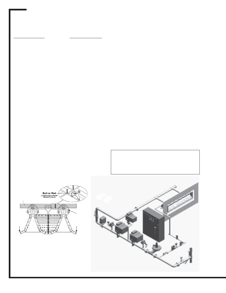
Gas Train
See piping layout below to identify various typical
system components.
Pipe size of gas line must be large enough to
assure ample fuel pressure at maximum system
capacity. Burner capacity is totally dependent on fuel
differential being maintained. (See capacity/specifica-
tion data for the actual fuel pressure required at the
burner to achieve its rated capacity.)
Clean fuel lines are essential to prevent blockage
of pipe train components or burner gas ports. All dirt,
scale and pipe dope should be blown out of any gas
line before actually connecting to the burner system.
Main shut-off cock should be upstream of both
system regulator and pilot line take-off. Use it to shut
off fuel to both pilot and main burner during extended
shutdown periods. Maxon Control Valves are not
intended for tight shutoff. Main system shut-off should
always be accomplished with a manual fuel cock.
Main gas regulator is essential to maintain a
uniform system supply pressure. A separate regulator
should be provided in the branch leading to each
burner system if more than one is served by a com-
mon main. Size regulator for full system capacity at
required pressure, including pipe train losses.
The gas train piping illustrated should be installed
as close to the burner as possible.
Pilot take-off should be upsteam of main gas
regulator, but downstream of main gas cock. It
normally includes pilot shut-off cock, pilot gas regula-
Typical Piloted System
Strap Iron
Frame
Support
Brackets
Air
Movement
Air
Movement
7