Grain Systems PNEG-526 User Manual
Page 183
50 Hanover Road, Florham Park, New Jersey 07932 www.ascovalve.com
Page 2 of 2
Form No.V5495R4
3. Replace valve bonnet and bonnet screw on valve body. Hand thread
screws a few turns into valve body, then torque bonnet screws in a
crisscross manner to 70 ± 8 in-lbs [8,0 ± 0,9 Nm].
4. Install solenoid base gasket and solenoid base sub-assembly.
Compress rider ring slightly to prevent damage when installing solenoid
base sub-assembly. Torque solenoid base sub-assembly to 175 ± 25
in-lbs [19,8 ± 2,8 Nm].
5. Install solenoid, see separate instructions and make electrical hookup.
WARNING: To prevent the possibility of death,
serious injury or property damage, check valve for
proper operation before returning to service. Also
perform internal seat and external leakage tests
with a nonhazardous, noncombustible fluid.
6. Restore line pressure and electrical power supply to valve.
7. After maintenance is completed, operate the valve a few times to be sure
of proper operation. A metallic click" signifies the solenoid is
operating.
ORDERING INFORMATION
FOR ASCO REBUILD KITS
Parts marked with an asterisk(*) in the
exploded view are supplied in Rebuild Kits.
S When Ordering Rebuild Kits for ASCO Valves, order the Rebuild Kit
number stamped on the valve nameplate.+
+ If the number of the kit is not visible, order by indicating the number of
kits required, and the Catalog Number and Serial Number of the valve(s)
for which they are intended.
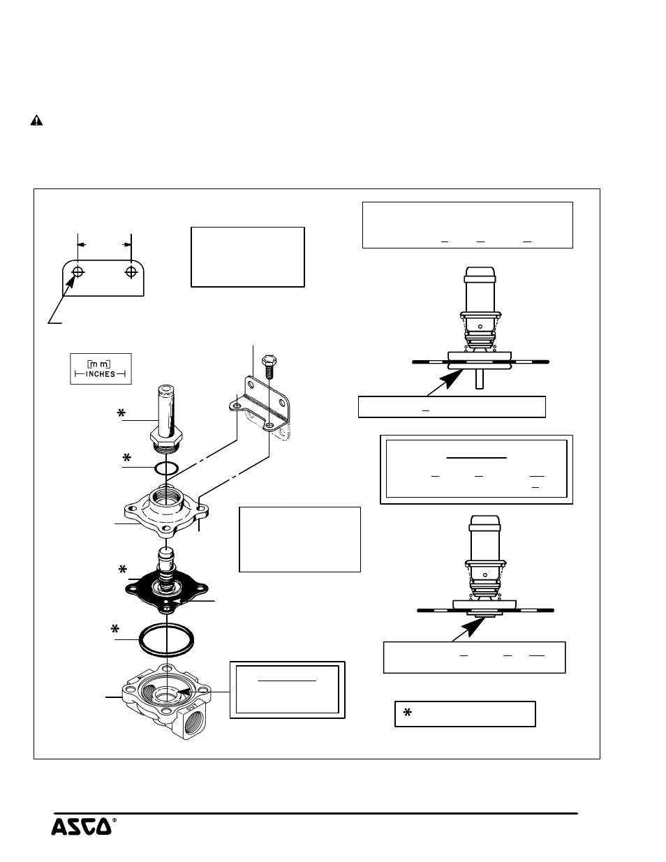
Figure 1. Series 8215 Valve Without Solenoid.
bleed hole
solenoid base
core/diaphragm
sub-assembly
body gasket
Torque bonnet screws
in a crisscross manner
Torque solenoid base
sub-assembly to
CAUTION
Do not damage
valve seat
1.656
[42.1]
.281 diameter
2 mounting holes
Partial view of
mounting bracket
solenoid base
sub-assembly
valve bonnet
valve body
mounting bracket
two positions
(optional feature)
gasket
Supplied in Rebuild Kit
Partial views of core/diaphragm
sub-assemblies showing the difference
CAUTION
(Locate bleed hole 45_
from valve outlet)
to 70$8 in-lbs
[8,0$0,9 Nm]
175$25 in-lbs
[19,8$2,8 Nm]
[
∅
7.1]
between 8215B, 8215C, & 8215G parts.
Series 8215B has a diaphragm disc.
8215C & 8215G parts are not
interchangable with 8215B
Series 8215C & 8215G do not
have a diaphragm disc.