Maintenance instructions, Corporation, Industrial combustion equipment and valves – Grain Systems PNEG-526 User Manual
Page 127
m
CORPORATION
MUNCIE, INDIANA, USA
INDUSTRIAL COMBUSTION EQUIPMENT AND VALVES
Maxon practices a policy of continuous product improvement. It reserves the right to alter specifications without prior notice.
Manual
Valve
A
Manual
Valve
B
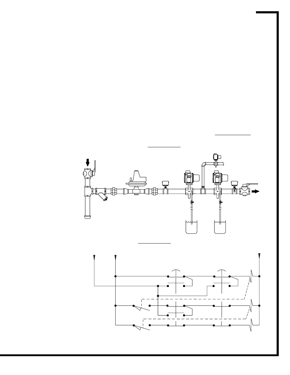
Shut-off
Valve
#1
Vent
Valve
Drip
Leg
Strainer
Shut-off Valve #2
Gas Pressure
Regulator
To Combustion
System
LGP
Switch
HGP
Switch
Maintenance Instructions
Page 6100-S-13
Electro-Mechanical Valves
2/00
Suggested leak test procedure for double-blocking shut-off valves with vent line
Example of a gas piping diagram for leak test with vent line
Example of a wiring diagram for leak test with vent line
(h) Secure test apparatus on valve #1.
(i) Remove the 1/4” pipe plug from downstream side
of shut-off valve #2. Install leak test apparatus.
(j) With an auxiliary power supply connected to valve
#1, open test apparatus and test valve for leak-
age. As a guideline, valve should be tested for 2
minutes per inch of pipe diameter. Large diameter
pipes or long piping runs between shut-off valves
may need additional testing time.
(k) If valve testing indicates leakage exceeding 15
bubbles per minute, perform pre-operational
exercising as outlined on Page 6100-S-2 and
retest the valve. If valve continues to exceed
allowable leakage limit, remove from service and
contact Maxon.
(l) Secure test apparatus on valve #2.
(m) Upon completion of valve leak testing, test all
other safety interlocks per manufacturer’s instruc-
tions and verify they are operational.
(n) Restore combustion system to operational
condition. Be sure to remove all auxiliary power
supplies and jumpers that may have been used
during testing.
Suggested leak test procedure for double-blocking shut-off valves (without vent line) - continued
If vent valve is
present, use auxil-
iary power supply to
power vent valve to
closed position
during this test
procedure. Follow
test instructions
above. Once test is
complete, be sure
vent valve is re-
stored to normal
operation.
Hot
LS-VV
LS-SV
From Flame
Safeguard
Shut-off Valve #2
Momentary Leak
Test Push Button
Shut-off Valve #1
Momentary Leak
Test Push Button
Shut-off
Valve #2
Shut-off
Valve #1
Vent
Valve
Neutral
NOTES:
Push button must be tamper
resistant.
LS-VV – Closes when Vent
Valve is fully closed
LS-SV – Closes when Shut-
off Valve #1 is fully open.
The “From Flame Safe-
guard” line is energized only
when sall conditions for
safe operation have been
satisfied.