Auxiliary signal switches, Field installation instructions, Corporation – Grain Systems PNEG-526 User Manual
Page 121: Industrial combustion equipment and valves, Fig. 1, Fig. 2, Fig. 3, Fig. 4, Wand position mounting brackets
m
CORPORATION
MUNCIE, INDIANA, USA
INDUSTRIAL COMBUSTION EQUIPMENT AND VALVES
Maxon practices a policy of continuous product improvement. It reserves the right to alter specifications without prior notice.
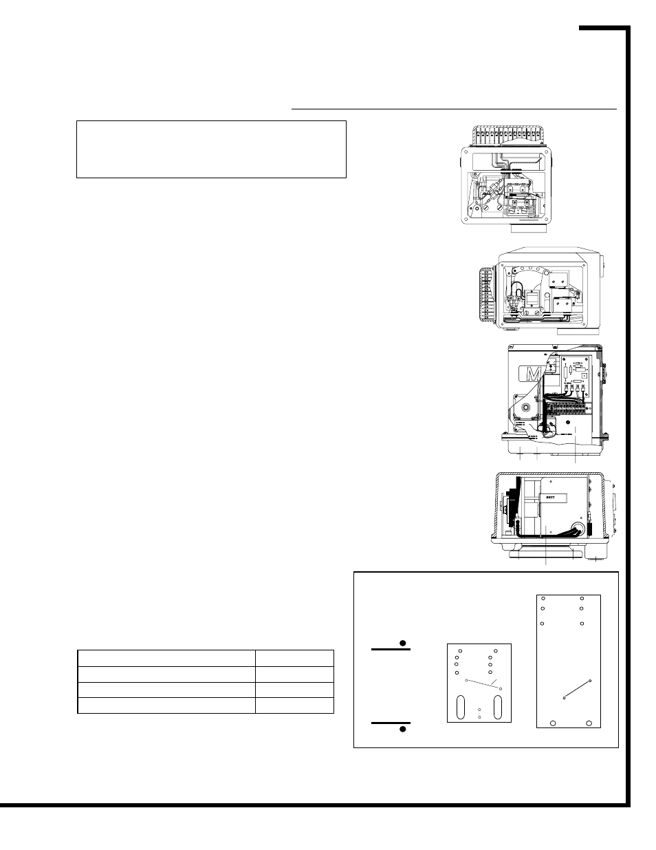
Auxiliary Signal Switches
Field Installation Instructions
NOTE: Instructions below are written for normally
closed valves. For normally open versions (STO-
M, STO-A, Fig. 1 & 2), reverse switch nomencla-
ture. (VOS becomes VCS and vice versa.)
General: Shut off fuel supply upstream of valve, then
de-energize valve electrically.
– Remove top or side cover to provide access, being
careful not to damage gasket.
– Compare with illustrations at right to identify YOUR
valve type.
To replace existing switches:
– Note wand position and mounting hole location
carefully, then remove 2 screws and lift existing switch.
– Install replacement switch in same mounting holes on
bracket and verify correct wand position.
– Replace existing wiring one connection at a time,
following original route and placement.
To add switches to existing valve:
– Check illustrations at right. If your valve uses a switch
mounting bracket as in Fig. 1 & 2, mount switches to
bracket using the mounting holes appropriate for valve
type and size.
– Position bracket so VCS wand just touches top of
actuator, then move downward slightly, depressing
wand until switch clicks, then tighten mounting screws
to hold this position.
– Pin bracket by drilling 1/8" dia. holes 1/4" deep into
bracket mounting pad through drive pin holes, then tap
drive pin in until flush.
– Route wires to wiring compartment as shown, then
complete wiring connections and clean out metal
drilling chips from previous procedure.
– Cycle valve, checking switch actuation points carefully.
(VCS actuates at top of stem stroke, VOS at bottom.)
Simultaneously the valve body must be tested for
switch continuity and seat leakage. Bend VOS switch
wands slightly if necessary to insure valve is opening
fully.
– Replace gasket and cover, then return valve to
service.
Fig. 1
.75" – 3"
non-CP
Remove
side cover plate.
Switches mount
on bracket. (See
"A" below)
Fig. 2
2.5" – 4" -CP
6" 808
Remove
side cover plate.
Switches mount
on bracket. (See
"B" below)
1/00
Page 6100-S-7
Electro-Mechanical Valves
Fig. 3
4" – 6" 7000
Remove 2-piece top cover.
Switches mount on support
stand.
Fig. 4
.375" – .75" 8700
Remove top cover.
Switches mount on actuator
frame
VOS switch
on front
VOS switch wand
should be actuated
from above.
VCS switch wand
should be actuated
from below.
Oil SOV &
2"-6" Gas
Bracket
Mounting
Slots
Drive
Pins
VCS switch mounts
on back of bracket
VOS switch
on front
1-1/2"
3/4", 1"
1-1/4"
A
For 1", 1.25" C.I.
& 2", 3" non-CP
Wand Position
Mounting Brackets
3",4",6"(-2)
3",4",6"(-2)
2-1/2"(-2)
2-1/2"(-1)
VCS Switch
on back
Bracket
Mounting
Holes
B
r
e
v
o
C
)
s
b
l
-
t
f
(
e
u
q
r
o
T
r
e
v
o
C
r
o
t
a
r
e
p
O
4
2
-
0
1
#
5
2
s
r
e
v
o
c
s
s
e
c
c
a
r
e
h
t
o
ll
A
0
2
-
"
5
2
.
0
5
e
t
a
l
P
r
e
v
o
C
s
s
e
c
c
A
d
e
d
n
e
t
x
E
0
2
-
"
5
2
.
6
9
NC
COM
#1 BLACK TO
#3 BLACK TO
BLACK TO MOTOR
TERMINAL #1
TERMINAL #3
NO
1
2
12
11
10
9
8
7
6
5
4
3
2
1
TO CLUTCH
SHUT