Installation instructions, Series np-le airflo, Burners – Grain Systems PNEG-526 User Manual
Page 97: Corporation, Industrial combustion equipment and valves, General, Supports
m
CORPORATION
MUNCIE, INDIANA, USA
INDUSTRIAL COMBUSTION EQUIPMENT AND VALVES
Maxon practices a policy of continuous product improvement. It reserves the right to alter specifications without prior notice.
Series NP-LE AIRFLO
®
Burners
Installation Instructions
General
Avoid bending or damaging the steel mixing plates
of your Series NP-LE AIRFLO
®
Burner during
uncrating and installation.
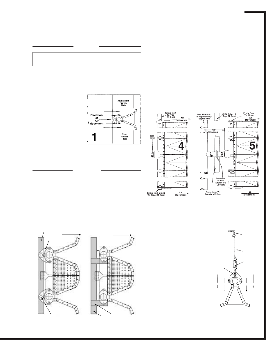
These burners are used
for the heating of fresh air
in motion. Mount the
burners so they fire parallel
to and in the same direc-
tion as the movement of
the air (see sketch 1 at
right).
Velocity and flow of air
at operating temperature
must be uniform. Minimum
silhouette profile plates of
6" should be installed in
Important: Do not discard packing material until
all loose items are accounted for.
duct to completely surround burner assembly.
Supports
Series NP-LE AIRFLO
®
Burner assemblies must be
adequately supported and positioned.
Avoid rigid mounting. Burner assembly expands
and contracts with temperature variations.
Maintain smooth, even air flow over the burner by
designing supports to provide minimum interference,
deflection and turbulence.
The sketches below show typical installation and
support methods:
Sketch 2 shows the burner suspended from a strap
iron frame using Maxon USB support brackets. Note
that rigid mounting is avoided by the bracket hole
which slips loosely over a bolt or steel rod attached to
the support. Gas piping would need independent
support.
Sketch 3 shows the burner assembly resting upon
angle iron brackets and not attached to them in any
way. Be sure the angle iron supports allow the burner
flanges to expand and contract. Gas manifolding
would be independently supported and prevent
forward movement of the burner.
the burner. If there are
multiple inlets, you must
avoid rigid connection by
using the oversize U-bolt
(loosely drawn up) illustrated.
Support for down-fired
burners can be accomplished
as shown in the illustration at
right. Always avoid rigid
mounting.
Sketch 6 shows Maxon
USB support brackets
suspending the burner from
an overhead angle iron.
Sketch 7 shows an alter-
nate arrangement which
offers the advantage of more
controlled positioning.
6/03
Sketch 4 shows simple strap iron used to support
the burner. Note that narrow edge of strap faces air
flow to avoid undue turbulence.
Sketch 5 shows gas manifolding used to support
Page 5550-S-1
Strap Iron
Frame
Maxon
Support
Brackets
Allow Space
for Burner
Expansion
Air
Movement
Air
Movement
Bolt or Rod
Long enough to permit
brackets to move with
burner expansion
Angle Iron
Support
Strap Iron
Frame
2
3
6
Angle
Iron
Support
Rod
Support
Brackets
3/4"
Hole
Air
Movement
Air
Movement