Installation instructions, Top assembly rotation – Grain Systems PNEG-526 User Manual
Page 117
m
CORPORATION
MUNCIE, INDIANA, USA
INDUSTRIAL COMBUSTION EQUIPMENT AND VALVES
Maxon practices a policy of continuous product improvement. It reserves the right to alter specifications without prior notice.
1
5
4
3
2
5
1
4
2
1
2
5
4
Electro-Mechanical Valves
Page 6100-S-3
Installation Instructions
(cont'd.)
Top Assembly Rotation
Maxon valves can and should be ordered in a con-
figuration compatible with planned piping, but if open/
shut indicator window is not visible and/or valve orienta-
tion is not proper, the top assembly can be rotated in
90° increments around the valve body centerline axis
by the following procedure:
1. Shut off all electrical power and close off up-
stream manual cock.
2. Remove wiring access cover plate [2] and
disconnect power lead wires. (Tag carefully for later
re-assembly.)
3. Remove conduit and electrical leads.
4. Note physical position of any signal switch
actuator wands on auxiliary signal switches (see
switch arrangement sketch).
5. Unscrew the two body bolts [4] screwed up from
the bottom to 1/4 inch. DO NOT completely re-
move. These bolts secure the valve body [3] to the
valve’s top assembly housing [5].
6. Gently lift the top assembly [5] (not more than
1/4" in height); just enough to break the seal
between the valve body assembly and the rubber
gasket adhering to the bottom of the top housing.
WARNING: LIFTING TOO FAR MAY DISLODGE
SOME SMALL PARTS INSIDE THE TOP
HOUSING, REQUIRING COMPLEX RE-
ASSEMBLY AND RETESTING BY TRAINED
FACTORY PERSONNEL.
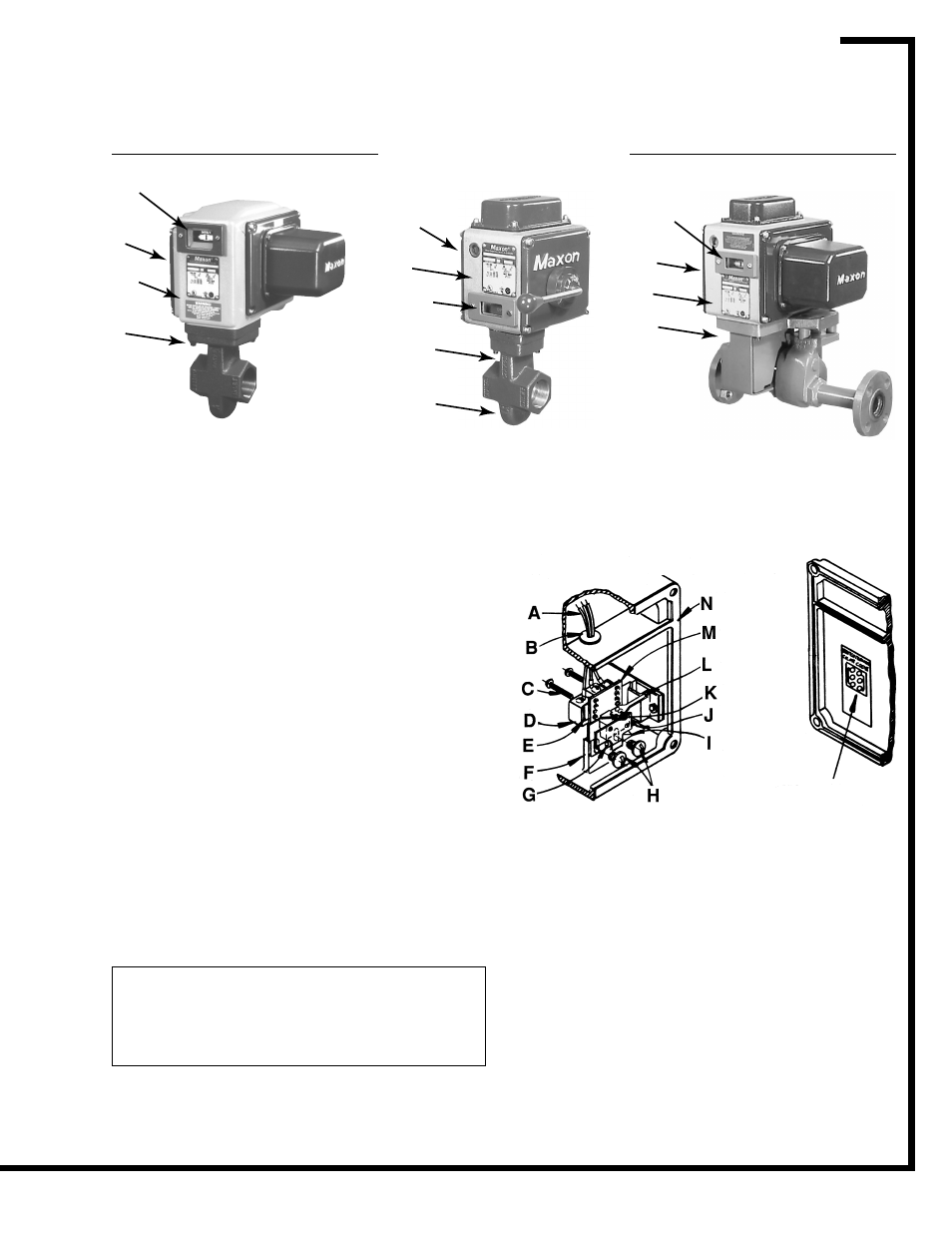
Series 808
Series 25300
with socket welded
nipples & flanges
Series 5000-CP
1/99
Wiring Diagram
Auxiliary Switch Arrangement
A– Number Coded Wires
H– Mounting Screws
B– Rubber Grommet
I – Spring Retainer Extension
C– Mounting Screws
J– Switch Wand
D– Normal (de-energized)
K– Actual (energized)
Position Switch
Position Switch
E– Insulating Barrier
L– Switch Wand
F– Bracket Mounting Pad
M– Switch Mounting Bracket
G– Drive Pin & Locating Hole
N– Gasket