2 factory set switch position, Hook switch, additional board, Switch positions – VEGA VEGACOM 557 Profibus FMS User Manual
Page 17
VEGACOM 557 Profibus FMS
17
Addressing of the process signals
DIL switch 1, additional board
Adjustment of the baud rate
Baud rate
(kBit/s)
S8
S7
S6
S5
S4
S3
S2
S1
9.6
off
off
off
off
off
off
off
off
19.2
off
off
off
off
off
off
off
on
93.75
off
off
off
off
off
off
on
off
187.5
off
off
off
off
off
off
on
on
500
off
off
off
off
off
on
off
off
1500
off
off
off
off
off
on
off
on
DIL switch 2, additional board
PROFIBUS address of VEGACOM 557
SW 8 SW 7 SW 6 SW 5 SW 4 SW 3 SW 2 SW 1
2
7
2
6
2
5
2
4
2
3
2
2
2
1
2
0
Example: = Address 32
SW 8 SW 7 SW 6 SW 5 SW 4 SW 3 SW 2 SW 1
off
off
on
off
off
off
off
off
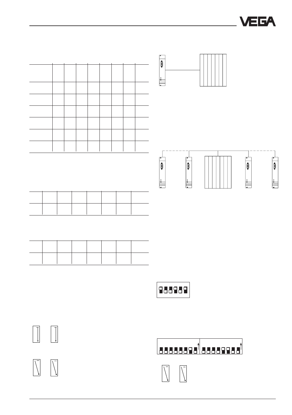
Hook switch, additional board
The hook switches are used to switch on the
bus termination resistances.
Switch positions
L R
1
L R
2
L R
1
L R
2
Bus termination "on"
Bus termination "off"
Note:
L = position left,
R = position right
Example 1
VEGACOM 557
PLC
Both hook switches "on"
If
one
VEGACOM 557 is connected to
one
PlC, the hook switches must be set to posi-
tion "on" (bus termination on).
Example 2
VEGACOM 557
VEGACOM 557
PLC
Both hook switches:
on
off
off
on
If
several
VEGACOM 557 are connected to
one
one
one
one
one PLC, the hook switches at the beginning
and end of the cable have to be in position
"on" (VEGACOM), and in position "off" on
VEGACOM 557 located in between.
3.2 Factory set switch position
DIL switch, basic board
DIL switch and hook switch, additional
board
1
ON
EDG
2 3 4 5 6
Transmission rate: 9.600 baud
1
ON
EPG
2
3
4
5
6
7
8
1
ON
EPG
2
3
4
5
6
7
8
DIL switch 2
DIL switch 1
L R
1
L R
2
Bus termination "off"